The comfort and safety in the house depends on the correct choice of the electrical wiring section. When overloaded, the conductor overheats and the insulation may melt, resulting in a fire or short circuit. But it is unprofitable to take a cross section larger than necessary, since the price of the cable increases.
In general, it is calculated depending on the number of consumers, for which the total power used by the apartment is first determined, and then the result is multiplied by 0.75. The PUE uses a table of loads for the cable section. From it, you can easily determine the diameter of the cores, which depends on the material and the passing current. As a rule, copper conductors are used.
The cross section of the cable core must exactly match the calculated one - in the direction of increasing the standard size range. It's most dangerous when it's low. Then the conductor constantly overheats, and the insulation quickly fails. And if you set the appropriate one, it will be triggered frequently.
If you overestimate the cross section of the wire, it will cost more. Although a certain margin is necessary, since in the future, as a rule, you have to connect new equipment. It is advisable to apply a safety factor of about 1.5.
Calculation of total power
The total power consumed by the apartment falls on the main input, which is included in the switchboard, and after it branches into lines:
- lighting;
- socket groups;
- separate powerful electrical appliances.
Therefore, the largest section of the power cable is at the input. On the outlet lines, it decreases, depending on the load. First of all, the total power of all loads is determined. This is not difficult, since it is indicated on the cases of all household appliances and in their passports.

All powers add up. Similarly, calculations are made for each contour. Experts suggest multiplying the amount by 0.75. This is due to the fact that at the same time all devices are not included in the network. Others suggest choosing a larger section. This creates a reserve for the subsequent commissioning of additional electrical appliances that may be purchased in the future. It should be noted that this cable calculation option is more reliable.

How to determine the wire size?
In all calculations, the cable section appears. It is easier to determine its diameter by using the formulas:
- S=π D²/4;
- D= √(4×S/π).
Where π = 3.14.

S = N × D² / 1.27.
Stranded wires are used where flexibility is required. Cheaper solid conductors are used in permanent installations.
How to choose a cable by power?
In order to select the wiring, the table of loads for the cable section is used:
- If the open type line is energized at 220 V, and the total power is 4 kW, a copper conductor with a cross section of 1.5 mm² is taken. This dimension is usually used for lighting wiring.
- With a power of 6 kW, conductors of a larger cross section are required - 2.5 mm². The wire is used for sockets to which household appliances are connected.
- A power of 10 kW requires the use of 6 mm² wiring. Usually it is intended for the kitchen, where an electric stove is connected. The supply to such a load is made on a separate line.
Which cables are best?
Electricians are well aware of the cable of the German brand NUM for office and residential premises. In Russia, brands of cables are produced that are lower in characteristics, although they may have the same name. They can be distinguished by the leakage of the compound in the space between the cores or by its absence.

The wire is produced monolithic and stranded. Each core, as well as the entire twist, is insulated from the outside with PVC, and the filler between them is made non-combustible:
- So, the NUM cable is used indoors, since the insulation on the street is destroyed by sunlight.
- And as an internal cable, the VVG brand is widely used. It is cheap and quite reliable. It is not recommended for laying in the ground.
- Wire brand VVG is made flat and round. Filler is not used between the cores.
- made with an outer shell that does not support combustion. The cores are made round up to a section of 16 mm², and above - sectoral.
- Cable brands PVS and ShVVP are made multi-wire and are used mainly for connecting household appliances. It is often used as home electrical wiring. It is not recommended to use stranded conductors on the street due to corrosion. In addition, the insulation cracks when bent at low temperatures.
- On the street, armored and moisture-resistant cables AVBShv and VBShv are laid underground. The armor is made of two steel tapes, which increases the reliability of the cable and makes it resistant to mechanical stress.
Determining the current load
A more accurate result is given by the calculation of the cable cross-section in terms of power and current, where the geometric parameters are related to electrical ones.

For home wiring, not only active load, but also reactive load should be taken into account. The current strength is determined by the formula:
I = P/(U∙cosφ).
A reactive load is created by fluorescent lamps and motors of electrical appliances (refrigerator, vacuum cleaner, power tools, etc.).
Current example
Let's find out what to do if it is necessary to determine the cross-section of a copper cable for connecting household appliances with a total power of 25 kW and three-phase machines for 10 kW. Such a connection is made by a five-core cable laid in the ground. The meals at home are from
Taking into account the reactive component, the power of household appliances and equipment will be:
- P life. = 25 / 0.7 = 35.7 kW;
- P rev. \u003d 10 / 0.7 \u003d 14.3 kW.
Input currents are determined:
- I life. \u003d 35.7 × 1000 / 220 \u003d 162 A;
- I rev. \u003d 14.3 × 1000 / 380 \u003d 38 A.
If you distribute single-phase loads evenly over three phases, one will have a current:
I f \u003d 162/3 \u003d 54 A.
I f \u003d 54 + 38 \u003d 92 A.
All appliances will not work at the same time. Taking into account the margin, each phase has a current:
I f \u003d 92 × 0.75 × 1.5 \u003d 103.5 A.
In a five-core cable, only phase cores are taken into account. For a cable laid in the ground, a conductor cross section of 16 mm² can be determined for a current of 103.5 A (table of loads for the cable cross section).
A more accurate calculation of the current strength saves money, since a smaller cross section is required. With a rougher calculation of the cable in terms of power, the cross section of the core will be 25 mm², which will cost more.
Cable voltage drop
Conductors have resistance that must be taken into account. This is especially important for long cable lengths or small cross-sections. PES standards have been established, according to which the voltage drop on the cable should not exceed 5%. The calculation is done as follows.
- The resistance of the conductor is determined: R = 2×(ρ×L)/S.
- The voltage drop is found: U pad. = I×R. In relation to the linear percentage, it will be: U% \u003d (U fall / U line) × 100.
The following notations are accepted in the formulas:
- ρ - resistivity, Ohm×mm²/m;
- S - cross-sectional area, mm².
The coefficient 2 shows that the current flows through two wires.
Example of cable calculation for voltage drop
- The wire resistance is: R \u003d 2 (0.0175 × 20) / 2.5 \u003d 0.28 Ohm.
- The strength of the current in the conductor: I \u003d 7000/220 \u003d 31.8 A.
- Carry voltage drop: U pad. = 31.8×0.28 = 8.9 V.
- Voltage drop percentage: U% \u003d (8.9 / 220) × 100 \u003d 4.1 %.
The carrying is suitable for the welding machine according to the requirements of the rules for the operation of electrical installations, since the percentage of voltage drop on it is within the normal range. However, its value on the supply wire remains large, which can adversely affect the welding process. Here it is necessary to check the lower permissible limit of the supply voltage for the welding machine.
Conclusion
To reliably protect the wiring from overheating when the rated current is exceeded for a long time, the cable cross-sections are calculated according to the long-term permissible currents. The calculation is simplified if the load table for the cable section is used. A more accurate result is obtained if the calculation is based on the maximum current load. And for stable and long-term operation, a circuit breaker is installed in the wiring circuit.
Why is it necessary to calculate the load on the cable?
One of the main parameters that determine the cost of a cable is its cross section. The larger it is, the higher its price. But if you buy an inexpensive wire, the cross section of which does not correspond to the loads in the circuit, the current density increases. Because of this, resistance increases and the release of thermal energy during the passage of electricity. Electricity losses increase, and the efficiency of the system decreases. Throughout the entire period of operation, the consumer pays for significant losses of electricity.
But this is not the only disadvantage of installing a cable with an incorrectly selected section. Due to the increased heat generation, the insulation of the wires heats up excessively - this reduces the life of the wires and often causes a short circuit.
Cable load calculation allows:
- Reduce electricity bills;
- Increase the service life of the wiring;
- Reduce the risk of a short circuit.
What losses occur when an electric current passes?
When calculating the load on the cable, you need to consider:
1. Loss of electric current when passing through the wiresThe movement of electricity from the current generator to receivers (household appliances, electrical equipment, lighting fixtures) is accompanied by the release of thermal energy. This physical process is of no use. The released heat heats the insulating shells, which leads to a reduction in their service life. They become more brittle and break quickly. Violation of the integrity of the insulation can cause a short circuit when the wires come into contact with each other, and when in contact with a person, a dangerous injury.
The conversion of electrical energy into thermal energy occurs due to resistance, which increases as the density of the passing current increases. This value is calculated by the formula:
J = I/S a/mm2
- I - current strength;
When installing internal wiring, the current density should not exceed 6 A/mm2. For other works, the calculation of the cable cross-section for current is carried out on the basis of the tables contained in the Rules for the Design and Technical Operation of Electrical Installations (PUE and PTEEP).
If the calculated density value is greater than the recommended one, it is necessary to buy a cable with a larger wire cross section. Despite the increase in the cost of wiring, such a solution is justified from an economic point of view. Choosing a cable for wiring with the optimal cross-sectional size will increase its safe operation life several times and reduce the loss of electricity when passing through the wires.
2. Losses due to electrical resistance of materialsThe resistance of materials that occurs during the transmission of electric current leads not only to the release of thermal energy and heating of the wires. There is also a loss of voltage, which negatively affects the operation of electrical equipment, household appliances and lighting fixtures.
When installing electrical wiring, it is also necessary to calculate the value of the line resistance (Rl). It is calculated by the formula:
- ρ is the specific resistance of the material from which the wire is made;
- l is the line length;
- S is the cross section of the wire.
The voltage drop is defined as ΔUl = IRl, and its value should be no more than 5% of the original, and for lighting loads - no more than 3%. If it is larger, it is necessary to choose a cable with a larger cross section or made of a different material, with a lower resistivity. In most cases, both from a technical and economic point of view, it is advisable to increase the cable cross-sectional area.
Choice of cable material
Our catalog of cable products in Brest includes a large selection of cables made of various materials:
- Copper
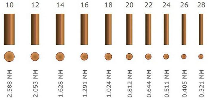
Copper has a very low resistivity (only gold is lower), so the conductivity of copper wires is much higher than that of aluminum. It does not oxidize, which significantly increases the period of effective operation. The metal is very flexible, the cable can be folded and coiled many times. Due to high ductility, it is possible to manufacture thinner cores (copper cores are made from 0.3 mm2, the minimum size of an aluminum core is 2.5 mm2).
The lower resistivity makes it possible to reduce the release of thermal energy during the passage of current, therefore, only copper wires are allowed to be used when laying internal wiring in residential premises.
- Aluminum
The specific resistance of aluminum is higher than that of gold, copper and silver, but lower than that of other metals and alloys.
The main advantage of an aluminum cable over a copper cable is that its price is several times lower. It is also much lighter, which facilitates the installation of electrical networks. When installing long-distance power networks, these characteristics are of decisive importance.
Aluminum does not corrode, but when exposed to air, a film forms on its surface. It protects the metal from exposure to atmospheric moisture, but practically does not conduct current. This feature makes it difficult to connect cables.

The main types of section calculation
The calculation of the loads on the wire must be performed according to all significant characteristics:
By power
The total power of all devices consuming electricity in a house, apartment, in a production workshop is determined. The power consumption of household appliances and electrical equipment is indicated by the manufacturer.
It is also necessary to take into account the electricity consumed by lighting fixtures. All electrical appliances at home rarely work at the same time, but the calculation of the cable cross-section by power is performed with a margin, which makes the wiring more reliable and safe. For industrial facilities, a more complex calculation is performed using demand and simultaneity factors.
By voltage
The calculation of the cable cross-section for voltage is based on the type of electrical network. It can be single-phase (in apartments of multi-storey buildings and most individual cottages) and three-phase (at enterprises). The voltage in a single-phase network is 220 V, in a three-phase network - 380 V.
If the total power of electrical appliances in the apartment is 15 kW, then for single-phase wiring this figure will be 15 kW, and for three-phase wiring it will be 3 times less - 5 kW. But when installing three-phase wiring, a cable with a smaller cross section is used, but containing not 3, but 5 cores.
By load
Calculation of the cable cross-section according to the load also requires the calculation of the total power of electrical equipment. It is desirable to increase this value by 20-30%. Wiring is carried out for a long time, and the number of household appliances in the apartment or equipment in the workshop may increase.
Then you should determine which equipment can be turned on at the same time. This figure can vary significantly in different houses. Some have a large number of household appliances or electrical equipment, which are used several times a month or a year. Others have only essential but frequently used electrical appliances in their home.
Depending on the value of the simultaneity factor, the power may differ slightly or several times from the load.
| Conductor cross section, mm2 | Cables with copper conductors | Cables with aluminum conductors | ||
|---|---|---|---|---|
| Voltage 220 V | Voltage 380 V | Voltage 220 V | Voltage 380 V | |
| 0,5 | 2,4 | - | - | - |
| 0,75 | 3,3 | - | - | - |
| 1 | 3,7 | 6,4 | - | - |
| 1,5 | 5 | 8,7 | - | - |
| 2 | 5,7 | 9,8 | 4,6 | 7,9 |
| 2,5 | 6,6 | 11 | 5,2 | 9,1 |
| 4 | 9 | 15 | 7 | 12 |
| 5 | 11 | 19 | 8,5 | 14 |
| 10 | 17 | 30 | 13 | 22 |
| 16 | 22 | 38 | 16 | 28 |
| 25 | 30 | 53 | 23 | 39 |
| 35 | 37 | 64 | 28 | 49 |
| Conductor cross section, mm2 | Cables with copper conductors | Cables with aluminum conductors | ||
|---|---|---|---|---|
| Voltage 220 V | Voltage 380 V | Voltage 220 V | Voltage 380 V | |
| 1 | 3 | 5,3 | - | - |
| 1,5 | 3,3 | 5,7 | - | - |
| 2 | 4,1 | 7,2 | 3 | 5,3 |
| 2,5 | 4,6 | 7,9 | 3,5 | 6 |
| 4 | 5,9 | 10 | 4,6 | 7,9 |
| 5 | 7,4 | 12 | 5,7 | 9,8 |
| 10 | 11 | 19 | 8,3 | 14 |
| 16 | 17 | 30 | 12 | 20 |
| 25 | 22 | 38 | 14 | 24 |
| 35 | 29 | 51 | 16 | - |
By current
To calculate the rated current, the value of the total load power is used. Knowing it, the maximum permitted current load is calculated by the formula:
- I - nominal current;
- P - total. power;
- U - voltage;
- cosφ - power factor.
Based on the obtained value, we find the optimal size of the cable section in the tables.
| Cross-section of conductors, mm | Copper conductors, wires and cables | |
|---|---|---|
| Voltage 220 V | Voltage 380 V | |
| 1,5 | 19 | 16 |
| 2,5 | 27 | 25 |
| 4 | 38 | 30 |
| 6 | 46 | 40 |
| 10 | 70 | 50 |
| 16 | 85 | 75 |
| 25 | 115 | 90 |
| 35 | 135 | 115 |
| 50 | 175 | 145 |
| 70 | 215 | 180 |
| 95 | 260 | 220 |
| 120 | 300 | 260 |
Important nuances for the correct calculation of the load on the cable
Theory calculation of electrical loads, the foundations of which were formed in the 1930s, aimed to determine a set of formulas that give an unambiguous solution for given electrical receivers and graphs (indicators) of electrical loads. In general, practice has shown the limitations of the "bottom-up" approach, based on the initial data for individual power consumers and their groups. This theory remains important when calculating the operating modes of a small number of power receivers with known data, when adding a limited number of graphs, when calculating for 2UR.
In the 1980s-1990s. the theory of calculating electrical loads increasingly adheres to non-formalized methods, in particular, the integrated method for calculating electrical loads, the elements of which are included in the "Guidelines for calculating the electrical loads of power supply systems" (RTM 36.18.32.0289). It is likely that working with information databases on electrical and technological indicators, cluster analysis and pattern recognition theory, construction of probabilistic and cenological distributions for expert and professional assessment can finally solve the problem of calculating electrical loads at all levels of the power supply system and at all stages of making a technical or investment decision .
Formalization of the calculation of electrical loads developed over the years in several directions and led to the following methods:
- empirical (method of demand coefficient, two-term empirical expressions, specific power consumption and specific load densities, technological schedule);
- ordered diagrams, transformed into calculation according to the calculated active power factor;
- actually statistical;
- probabilistic modeling of load curves.
Demand factor method
The demand factor method is the simplest, most widespread, and the calculation of loads began with it. It consists in using the expression (2.20): according to the known (given) value Ru and the tabular values given in the reference literature (see examples in Table 2.1):
 The value of Kc is assumed to be the same for power receivers of the same group (operating in the same mode), regardless of the number and power of individual receivers. The physical meaning is the fraction of the sum of the rated powers of electrical receivers, which statistically reflects the maximum practically expected and occurring mode of simultaneous operation and loading of some indefinite combination (implementation) of installed receivers.
The given reference data for Kc and Kp correspond to the maximum value, and not to the mathematical expectation. Summing up the maximum values, and not the averages, inevitably overestimates the load. If we consider any group of EPs of the modern electrical economy (and not the 1930-1960s), then the conventionality of the concept of “homogeneous group” becomes obvious. Differences in the value of the coefficient - 1:10 (up to 1:100 and above) - are inevitable and are explained by the cenological properties of the electrical economy.
In table. 2.2 shows the LGS values characterizing the pumps as a group. When researching KQ4 further, for example only for raw water pumps, there may also be a spread of 1:10.
It is more correct to learn to evaluate Kc as a whole for the consumer (section, department, workshop). It is useful to perform an analysis of the calculated and actual values for all technology-related objects of the same level of the power supply system, similar to Table. 1.2 and 1.3. This will create a personal information bank and ensure the accuracy of calculations. The method of specific power consumption is applicable for sections (installations) 2UR (second, third ... Level of the Energy System), departments of ZUR and workshops 4UR, where technological products are homogeneous and quantitatively change little (increase in output reduces, as a rule, specific electricity consumption Aui).
Method "maximum power"
In real conditions, continuous operation of the consumer does not mean the constancy of the load at the point of its connection at a higher level of the power supply system. As a statistic value Lud, determined for some previously identified object by power consumption A and volume L /, there is some averaging over a known, often monthly or annual, interval. Therefore, the application of formula (2.30) gives not the maximum, but the average load. To select the ZUR transformers, one can take Рav = Рmax. In the general case, especially for 4UR (workshop), it is necessary to take into account Kmax as T to accept the actual annual (daily) number of hours of production operation with the maximum use of active power.

Method of specific load densities
The method of specific load densities is close to the previous one. The specific power (load density) y is set and the area of the building of the structure or section, department, workshop is determined (for example, for machine-building and metalworking shops y = 0.12 ... 0.25 kW/m2; for oxygen converter shops y = = 0.16 ... 0.32 kW/m2). A load exceeding 0.4 kW / m2 is possible for some areas, in particular, for those where there are single power receivers with a unit power of 1.0 ... 30.0 MW.
Process chart method
The technological schedule method is based on the schedule of the unit, line or group of machines. For example, the operation schedule of an arc steel-smelting furnace is specified: the melting time (27 ... 50 min), the oxidation time (20 ... 80 min), the number of melts, technological linkage with the operation of other steel-smelting units are indicated. The graph allows you to determine the total electricity consumption per melt, average per cycle (taking into account the time until the next melt), and the maximum load for calculating the supply network.
Ordered chart method
The method of ordered diagrams, which was applied in the directive in the 1960s - 1970s. for all levels of the power supply system and at all stages of design, in the 1980s-1990s. was transformed into the calculation of loads according to the calculated active power factor. If there is data on the number of power receivers, their power, modes of operation, it is recommended to use it to calculate the elements of the power supply system 2UR, ZUR (wire, cable, busbar, low-voltage equipment) supplying a power load with voltage up to 1 kV (simplified for the effective number of receivers of the entire workshop, i.e. for a network with a voltage of 6 - 10 kV 4UR). The difference between the method of ordered diagrams and calculation by the rated active power factor lies in the replacement of the maximum factor, always understood unambiguously as the ratio Pmax / Rav (2.16), by the rated active power factor Ap. The order of calculation for the node element is as follows:
A list (number) of power receivers is compiled, indicating their nominal PHOMi (installed) power;
The work shift with the highest electricity consumption is determined and the characteristic day is agreed (with technologists and the power system);
The features of the technological process that affect power consumption are described, power receivers with high load unevenness are distinguished (they are considered differently - according to the maximum effective load);
The following electrical receivers are excluded from the calculation (list): a) low power; b) reserve according to the conditions for calculating electrical loads; c) included sporadically;
Groups m of electrical receivers having the same type (mode) of operation are determined;
From these groups, subgroups are distinguished that have the same value of the individual utilization factor a:u/;
Electric receivers of the same operating mode are allocated and their average power is determined;
The average reactive load is calculated;
There is a group coefficient of utilization Kn of active power;
The effective number of power receivers in a group of n power receivers is calculated:
where the effective (reduced) number of power receivers is the number of power receivers of the same power that are homogeneous in terms of operation, which gives the same value of the calculated maximum P as a group of power receivers that are different in power and mode of operation.
With the number of power receivers in a group of four or more, it is allowed to take pe equal to n (the actual number of power receivers), provided that the ratio of the rated power of the largest power receiver Pmutm to the rated power of the smaller power receiver Dom mm is less than three. When determining the value of p, it is allowed to exclude small power receivers, the total power of which does not exceed 5% of the rated power of the entire group;
According to the reference data and the heating time constant T0, the value of the calculated coefficient Kp is taken;
The calculated maximum load is determined:
Electrical loads individual nodes of the power supply system in networks with voltages above 1 kV (located at 4UR, 5UR) were recommended to be determined similarly with the inclusion of losses in.
The calculation results are summarized in a table. This completes the calculation of loads according to the calculated active power factor.
The calculated maximum load of a group of electrical receivers Рmax can be found in a simplified way:
where Рnom - group rated power (the sum of rated powers, with the exception of reserve ones according to the calculation of electrical loads); Рav.cm ~ average active power for the busiest shift.
The calculation according to formula (2.32) is cumbersome, difficult to understand and apply, and most importantly, it often gives a double (or more) error. The method overcomes non-Gaussian randomness, uncertainty and incompleteness of the initial information with the following assumptions: power receivers of the same name have the same coefficients, standby motors are excluded according to the conditions of electrical loads, the utilization factor is considered independent of the number of power receivers in the group, power receivers with an almost constant load schedule are distinguished, the smallest ones are excluded from the calculation power receivers. The method is not differentiated for different levels of the power supply system and for different stages of implementation (coordination) of the project. The calculated coefficient of the maximum active power Kmax is taken to tend to unity with an increase in the number of power receivers (in fact, this is not the case - statistics do not confirm this. For a department where there are 300 ... ,2… 1.4). The introduction of market relations, leading to automation, a variety of output, moves electrical receivers from group to group.
The statistical definition of Rav.cm for operating enterprises is complicated by the difficulty of choosing the busiest shift (transfer of the start of work for different categories of workers within a shift, four-shift work, etc.). Uncertainty appears in the measurements (superimposition on the administrative-territorial structure). Restrictions on the part of the power system lead to regimes when the maximum load Ptx occurs in one shift, while the consumption of electricity is greater in another shift. When determining Рр, it is necessary to abandon Рср.см, excluding intermediate calculations.
A detailed consideration of the shortcomings of the method is caused by the need to show that the calculation of electrical loads, based on classical ideas about the electrical circuit and load curves, theoretically cannot provide sufficient accuracy.
Statistical methods for calculating electrical loads are consistently defended by a number of specialists. The method takes into account that even for one group of mechanisms operating in a given production area, the coefficients and indicators vary widely. For example, the inclusion factor for non-automatic machine tools of the same type varies from 0.03 to 0.95, loading A3 - from 0.05 to 0.85.
The task of finding the maximum of the Рр function on a certain time interval is complicated by the fact that power receivers and consumers with different operating modes are fed from 2UR, ZUR, 4UR. The statistical method is based on measuring the loads of lines supplying characteristic groups of power receivers, without referring to the operating mode of individual power receivers and the numerical characteristics of individual graphs.
(xtypo_quote) The method uses two integral characteristics: the general load average PQp and the general standard deviation, where the dispersion DP is taken for the same averaging interval. (/xtypo_quote)
The maximum load is determined as follows:

The value of p is taken to be different. In probability theory, the three-sigma rule is often used: Pmax = Pavg ± Za, which, with a normal distribution, corresponds to a limiting probability of 0.9973. The probability of exceeding the load by 0.5% corresponds to р = 2.5; for p = 1.65, a 5% probability of error is provided.
The statistical method is a reliable method for studying the loads of an operating industrial enterprise, providing a relatively correct value of the maximum load Pi (miiX) declared by an industrial enterprise during the hours of the maximum in the power system. In this case, it is necessary to assume a Gaussian distribution of the operation of electrical receivers (consumers).
The method of probabilistic modeling of load curves involves a direct study of the probabilistic nature of successive random changes in the total load of groups of power receivers over time and is based on the theory of random processes, with the help of which autocorrelation (formula (2.10)), cross-correlation functions and other parameters are obtained. Studies of the work schedules of electrical receivers of large unit capacity, the work schedules of workshops and enterprises determine the prospects for the method of controlling power consumption modes and leveling the schedules.
For durable and reliable operation of the electrical wiring, it is necessary to choose the right cable cross-section. To do this, you need to calculate the load in the power grid. When making calculations, it must be remembered that the calculation of the load of one electrical appliance and a group of electrical appliances differ somewhat.
Calculation of the current load for a single consumer
The choice of a circuit breaker and the calculation of the load for a single consumer in a 220 V residential network is quite simple. To do this, we recall the main law of electrical engineering - Ohm's law. After that, having set the power of the electrical appliance (indicated in the passport for the electrical appliance) and given the voltage (for household single-phase networks 220 V), we calculate the current consumed by the electrical appliance.
For example, a household electrical appliance has a supply voltage of 220 V and a nameplate power of 3 kW. We apply Ohm's law and get I nom \u003d P nom / U nom \u003d 3000 W / 220 V \u003d 13.6 A. Accordingly, to protect this consumer of electrical energy, it is necessary to install a circuit breaker with a rated current of 14 A. Since there are none, it is selected the nearest larger one, that is, with a rated current of 16 A.
Calculation of current load for groups of consumers
Since the power supply of electricity consumers can be carried out not only individually, but also in groups, the issue of calculating the load of a group of consumers becomes relevant, since they will be connected to one circuit breaker.
To calculate a group of consumers, the demand coefficient K s is introduced. It determines the probability of simultaneous connection of all consumers of the group for a long time.
The value of K c = 1 corresponds to the simultaneous connection of all electrical appliances of the group. Naturally, the inclusion of all consumers of electricity in an apartment at the same time is extremely rare, I would say incredible. There are whole methods for calculating demand coefficients for enterprises, houses, entrances, workshops, and so on. The demand factor of an apartment will vary for different rooms, consumers, and will also largely depend on the lifestyle of residents.
Therefore, the calculation for a group of consumers will look somewhat more complicated, since this coefficient must be taken into account.
The table below shows the demand factors for electrical appliances in a small apartment:

The demand coefficient will be equal to the ratio of the reduced power to the total K from the apartment = 2843/8770 = 0.32.
We calculate the load current I nom \u003d 2843 W / 220 V \u003d 12.92 A. We select an automatic machine for 16A.
Using the above formulas, we calculated the operating current of the network. Now you need to select the cable section for each consumer or consumer groups.
PUE (rules for electrical installations) regulates the cable cross-section for various currents, voltages, powers. Below is a table from which, according to the estimated power of the network and current, the cable section for electrical installations with a voltage of 220 V and 380 V is selected:

The table shows only the cross sections of copper wires. This is due to the fact that aluminum wiring is not laid in modern residential buildings.
Also below is a table with the range of capacities of household electrical appliances for calculation in networks of residential premises (from the standards for determining the design loads of buildings, apartments, private houses, microdistricts).

Typical cable size selection
In accordance with the cable section, circuit breakers are used. Most often, the classic version of the wire section is used:
- For lighting circuits with a cross section of 1.5 mm 2;
- For circuits of sockets with a section of 2.5 mm 2;
- For electric stoves, air conditioners, water heaters - 4 mm 2;
A 10 mm 2 cable is used to enter the power supply into the apartment, although in most cases 6 mm 2 is enough. But a section of 10 mm 2 is chosen with a margin, so to speak, with the expectation of a larger number of electrical appliances. Also, a common RCD with a trip current of 300 mA is installed at the input - its purpose is fire, since the trip current is too high to protect a person or animal.
To protect people and animals, RCDs with a tripping current of 10 mA or 30 mA are used directly in potentially unsafe rooms, such as a kitchen, bath, and sometimes room outlet groups. The lighting network, as a rule, is not supplied with an RCD.
There is always a lot of work in the personnel department. It is a pity that not all leaders understand this. Often, neither the administration nor the personnel themselves can objectively assess the level of workload. How to approach this difficult problem and not allow additional functions to be loaded onto frames? How many employees should be recruited into the HR department if the number of employees increases?
The first attempt to find a standard for the number of personnel officers refers us to the 1991 document "Intersectoral time standards for staffing and accounting work." These standards have never been reissued, and although they still serve as a guideline for calculating the load, they are clearly outdated. Tools such as a PC at every workplace, 1C and other software simply could not be taken into account in 1991. How to be? There are two real ways to solve the problem.
The first way is the rationing of labor
This is a very time-consuming process, but the result will be quite accurate and expressed in the language of numbers. And leaders understand the language of numbers well. So, :
- We highlight the main workflows. It is important not to take into account the task as a whole, but to break it down into its components. For example, hiring consists of copying documents, entering information into the system, drawing up an employment contract, familiarizing the employee with local acts, and so on.
- We determine the time costs for each process. We note the time required to obtain the desired result of the work. The time to complete each operation is measured by the rationer or the person who is entrusted with the rationing.
- We find the approximate number of described processes per month or year. The average number of admissions, transfers, dismissals, sick leaves, and so on.
- We multiply the number of operations by the time of their execution.
For example, the total time required to issue a sick leave is 15 minutes, the average number of sick leaves per year is 50 pieces. Total: 15 × 50 = 750 minutes, or 12.5 hours. We do this in every area of work.
- We add time for unplanned labor costs - consulting employees, compiling lists, etc. In this case, we proceed from the realities of a particular organization.
- The resulting total time in hours is divided by 8 and we get the number of days required to complete the work.
For clarity, we give an example of an approximate calculation of the time for hiring a new employee.
When applying this method, take into account computer breaks, meetings, business trips, vacations and illnesses of employees of the personnel department.
Advantages
A compelling picture that clearly shows the number of tasks performed by the HR department and their complexity.
Flaws
The inability to accurately plan the amount of future work, which causes errors. It is reasonable to add to the result obtained additional time for unforeseen functions and force majeure.
The second way - we proceed from the number of personnel
This method is used most often, since it is quite logical that with an increase in the number of staff, the load on the personnel department increases. But information alone on the number of employees is clearly not enough; a list of functions assigned to personnel officers should be determined. Often their tasks include:
- registration of VHI policies and related documents.
But even without these additional functions, one personnel officer is usually hired for every 150-200 staff members. This is a very approximate calculation, since the fluidity and the actual volume of processed documents are not taken into account. In addition, the specifics of the organization's activities can both reduce the load and increase it. Enterprises with, where medical examinations and additional benefits are required, are more complex in terms of personnel records.
How to calculate employee turnover
If you decide to build on the number of staff, and this method seems simpler and more convenient to you, you should still calculate the turnover over the past period and formulate the main tasks.
Fluidity is found by a simple formula:
Kt \u003d (number of dismissed) × 100 / (average headcount).
Example:
During the year, the company fired 23 people, the average number is 150 people, the calculation of turnover:
Flow coefficient = 23 × 100 / 150 = 15.33.
The rate of turnover depends on the scope of the organization, material stability, seasonality and management policy. In general, a ratio of 10-20 percent is considered normal. The higher the turnover, the greater the burden on personnel workers, and if it is significantly higher than the average, this is a reason to increase the number of personnel departments.
So, to use this method, we take into account:
- Number.
- Fluidity.
- Additional functions.
With low turnover and a small amount of workload in the form of added tasks, having one HR worker per 150 people seems to be sufficient.
Advantages
Insignificant labor costs and the ability to have a temporary reserve of man-hours for unforeseen situations.
Flaws
Low accuracy and the need to regularly prove the correctness of the calculation, since the visibility of the results is low.


