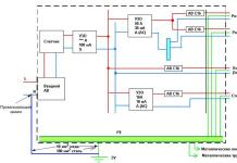
A capacitor is an electronic component designed to store electrical energy. By the nature of the work, it belongs to passive elements. Depending on the mode of operation in which the element operates, capacitors are distinguished constant capacity and variable(as an option - tuning). By type of operating voltage: polar - for operation with a certain polarity of connection, non-polar - can be used in both AC and DC circuits. In a parallel connection, the resulting capacitance is summed. This is important to know when selecting the required capacity for an electrical circuit.
To start and operate asynchronous motors in a single-phase AC circuit, capacitors are used:
- Launchers.
- Workers.
The starting capacitor is designed for short-term work- engine starting. After the engine reaches operating frequency and power, the starting capacitor is turned off. Further work occurs without the participation of this element. This is necessary for certain engines, the operating scheme of which provides for a start-up mode, as well as for conventional engines, which at the time of start-up have a load on the shaft that prevents the free rotation of the rotor.

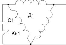
Use a button to start the engine Kn1, which switches the starting capacitor C1 for the time required for the electric motor to reach the required power and speed. After this, capacitor C1 is turned off and the motor operates due to a phase shift in the working windings. The operating voltage of such a capacitor must be selected taking into account the coefficient of 1.15, i.e. for a 220 V network, the operating voltage of the capacitor should be 220 * 1.15 = 250 V. The capacity of the starting capacitor can be calculated from the initial parameters of the electric motor.

The run capacitor is connected to the circuit at all times and acts as a phase-shifting circuit for the motor windings. For reliable operation of such an engine, it is necessary to calculate the parameters of the working capacitor. Due to the fact that the capacitor and the electric motor winding create an oscillatory circuit, at the moment of transition from one phase of the cycle to another, an increased voltage appears on the capacitor, exceeding the supply voltage.
The capacitor is constantly exposed to this voltage, and when choosing its value, it is necessary to take this factor into account. When calculating the voltage of the working capacitor, take a coefficient of 2.5-3. For a 220 V network, the operating capacitor voltage should be 550-600 V. This will provide the necessary voltage reserve during operation.
When determining the capacity of this element, the engine power and the winding connection diagram are taken into account.
There are two types of connection of the windings of a three-phase motor:
- Triangle.
- Star.
Each of these connection methods has its own calculation.
Triangle: Wed=4800*Ip/Up.
Example: for a 1 kW motor - the current is approximately 5A, voltage 220 V. Av = 4800 * 5/220. The capacity of the working capacitor will be 109 mF. Round to the nearest integer – 110 mF.
Star: C р=2800*Ip/Up.
Example: 1000 W motor - current is approximately 5 A, voltage 220 V. Av = 2800 * 5/220. The capacity of the working capacitor will be 63.6 mF. Round to the nearest integer - 65 mF.
From the calculations it is clear that the method of connecting the windings greatly affects the size of the working capacitor.
Comparison of running and starting capacitors
Comparative table of the use of capacitors for asynchronous motors connected to a voltage of 220 V.
| WORKER | LAUNCHER | |
| Where is it used? | In the circuit of working windings of an asynchronous motor | In the starting circuit |
| Functions performed | Creating a rotating electromagnetic field to operate an electric motor | Phase shift between the starting and working windings, starting the engine under load |
| Working hours | From switching on to finishing work | During startup until the desired mode is reached. |
| Capacitor type | MBGO, MBGCH and the like of the required rating and voltage 1.15 higher than the supply voltage | MBGO, MBGCH and the like of the required rating and for an operating voltage 2-3 times higher than the supply voltage |

Due to the fact that these types of capacitors have relatively large dimensions and cost, polar (oxide) capacitors can be used as a working and starting capacitor.
They have the following advantage: despite their small dimensions, they have a much larger capacity than paper ones.
Along with this, there is a significant drawback: they cannot be connected directly to the AC network. For use in conjunction with a motor, you need to use semiconductor diodes. The connection circuit is simple, but it has a drawback: the diodes must be selected in accordance with the load currents. At high currents, diodes must be installed on radiators. If the calculation is incorrect, or the heat sink area is smaller than required, the diode may fail and allow alternating voltage to pass into the circuit. Polar capacitors are designed for constant voltage and when they are exposed to alternating voltage, they overheat, the electrolyte inside them boils and they fail, which can cause harm not only to the electric motor, but also to the person servicing this device.
Voltage 220 V is a life-threatening voltage. In order to comply with the rules for the safe operation of consumer electrical installations, and to preserve the life and health of persons operating these devices, the use of these connection circuits must be carried out by a specialist.
If you want to connect a three-phase electric motor to a regular electrical network, you will need to create an electrical circuit for a phase shift. The basis of such a circuit can be a capacitor. It is also used for single-phase motors to facilitate its starting.
What is a capacitor
This is a device for storing electrical charge. It consists of a pair of conductive plates located at a small distance from each other and separated by a layer of insulating material.
The following types of electrical charge storage devices are widely used:
- Polar. They operate in circuits with constant voltage and are connected in accordance with the polarity indicated on them.
- Non-polar. They work in circuits with alternating voltage, you can connect them in any way you like
- Electrolytic. The plates are thin oxide films on a sheet of foil.

Electrolytic ones are better suited than others to serve as a capacitor for starting an electric motor.
Description of types of capacitors
Various types of electric motors correspond to drives that are suitable for their characteristics.
So, for low-frequency high-voltage (50 hertz, 220-600 volts) motors, an electrolytic capacitor is well suited. Such devices have a high capacity, reaching up to 100 thousand microfarads. It is necessary to carefully monitor the polarity, otherwise a fire may occur due to overheating of the plates.
Non-polar drives do not have such restrictions, but they cost several times more.

In addition to those listed above, vacuum, gas, and liquid devices are also produced, but they are not used as a starting or running capacitor in an electric motor connection circuit.
Selection of capacity
In order to maximize the efficiency of the electric motor, it is necessary to calculate a number of parameters of the electrical circuit, and above all the capacitance.
For run capacitor
There are complex and accurate calculation methods, but at home it is enough to estimate the parameter using an approximate formula.
For every 100 watts of electrical power of a three-phase electric motor, there should be 7 microfarads.
It is also unacceptable to apply voltage to the phase stator winding that exceeds the rated voltage.
For starting capacitor
If the electric motor must be started when there is a high load on the drive shaft, then the running capacitor will not cope, and a starting capacitor will need to be connected during startup. After reaching operating speed, which happens on average in 2-3 seconds, it is turned off manually or by an automatic device. Special buttons for turning on electrical equipment are available that automatically open one of the circuits after a specified delay time.
It is unacceptable to leave the startup drive connected in operating mode. Phase imbalance of currents can lead to overheating and fire of the motor. When determining the capacity of the starting device, it should be 2-3 times higher than that of the worker. At the same time, when starting, the torque of the electric motor reaches its maximum value, and after overcoming the inertia of the mechanism and gaining speed, it decreases to the nominal value.
To set the required capacitance, the capacitors for starting the electric motor are connected in parallel. The capacity is summed up.
Simple ways to connect an electric motor
The easiest way to connect a three-phase electric motor to a household electrical network is to use a frequency converter. Power losses will be minimal, but such a device often costs more than the engine itself.
A frequency converter will only become cost-effective if there is a large volume of equipment used.
Another method uses the winding of the asynchronous electric motor itself to convert the supply voltage. The scheme will be bulky and massive . The capacitor for starting the electric motor is connected according to one of two popular schemes
- triangle;
- star.

Connecting the motor according to the star and delta circuits
When implementing connections using these methods, it is important to minimize power losses.
Delta connection diagram
The circuit is quite simple; to make it easier to understand, we will designate the motor contacts with the symbols A - zero, B - working and C - phase
The power cord is connected with a brown conductor to pin A, and one of the capacitor leads should also be connected there. The second terminal of the device is connected to pin I, and the blue conductor of the power cord is connected to pin C.
In the case of a small electric motor power, not exceeding 1.5 kilowatts, it is permissible to connect only one capacitor; a starting capacitor is not needed.
If the power is higher and the load on the shaft is significant, then two devices connected in parallel are used.
Star connection diagram
If there are 6 terminals on the electric motor terminal block, you should ring them separately and determine which terminals are connected to each other. In the motor passport you need to find the purpose of the pins. After this, the circuit is reconnected, forming the usual “triangle”.
For this purpose, the jumpers are removed and the contacts are assigned symbols from A to F. Next, the contacts are connected in series: A and D, B and E, C and F.
Now contacts D, E and F will become the neutral, working and phase wires, respectively. The capacitor is connected to them in exactly the same way as in the previous case.
When you turn it on for the first time, you need to carefully ensure that the windings do not overheat. In this case, you should immediately turn off the device and determine the cause of overheating.
Operating voltage
After capacitance, voltage is the most important parameter. If you take too much voltage margin, the dimensions, weight and price of the entire device will increase significantly. Even worse is to take devices that do not have enough operating voltage. Such use will lead to their rapid wear, failure, and breakdown. This may cause a fire or even an explosion.
The optimal voltage margin is 15-20%.
Important! For paper dielectric capacitors in AC circuits, the rated voltage specified for DC must be divided by 3.
If 600 volts is indicated, then such capacitors can be safely used in AC circuits up to 300 volts.
Using Electrolytic Capacitors
Capacitors with a dielectric made of paper are characterized by a low specific capacitance and significant dimensions. For an engine of even not the highest power, they will take up a lot of space. Theoretically, they can be replaced by electrolytic ones, which have several times higher specific capacity.

To do this, the electrical circuit will have to be supplemented with several elements: diodes and resistors. This option is not bad for an occasionally running engine. If long-term loads are planned, then it is better to abandon saving space and weight - if the diode accidentally fails, it will begin to pass alternating current to the drive, which will lead to its breakdown and explosion.
The solution can be polypropylene capacitors with metal coating of the SVV series, designed for use as starting capacitors.
How to choose a capacitor for a three-phase electric motor
To calculate the capacitance of the main capacitor, use the formula:
- k-coefficient taken as 4800 for the “triangle” circuit and 2800 for the “star” circuit;
- Iφ is the stator current, it is taken from the passport or plate on the case;
- U is the network voltage.

The result is obtained in microfarads. Instead of an exact formula, you can apply the rule: for every 100 watts of power - 7 microfarads of capacity.
If, at start-up, the engine has to overcome a large moment of inertia of the equipment connected to the shaft, then a starting capacitor is connected to help the main one during start-up and at the set rated speed.
The capacity of the starting storage device is 2-3 times larger than the main one.

After entering the mode, it must be turned off - manually or using automation. If there is no device exactly suitable for the calculated capacitance, the capacitors can be connected in parallel.
How to choose a starting capacitor for a single-phase electric motor
Before use in the starting circuit, the capacitor is checked for serviceability with a tester. When selecting a working capacitor, you can apply the same approximate rule of a-7 microfarads per 100 watts of rated electrical power. The starting capacity is also taken 2-3 times higher.
When selecting a 220-volt capacitor, you should choose models with a rating of at least 400. This is explained by transient electromagnetic processes during startup, which give short-term inrush voltage surges of up to 350-550 volts.
Single-phase asynchronous electric motors are often used in household electrical appliances and power tools. To start such devices, especially under load, a starting winding and a phase shift are required. For this, a capacitor is used, connected according to one of the known circuits.

If the start is carried out with overcoming a large moment of inertia, connect a starting capacitor.
Why is a single-phase electric motor started through a capacitor?
The stator of an electric motor with a single winding, when passing alternating current, will not be able to start rotating, but will only begin to tremble. To start rotation, a starting winding is placed perpendicular to the main winding. A phase shifting component such as a capacitor is included in this winding circuit. The electromagnetic fields of these two windings, applied to the rotor with a phase shift, will ensure the start of rotation.
In a three-phase motor, the windings are already placed at angles of 120 °. The electromagnetic fields they induced in the rotor are oriented accordingly. To start rotation, it is enough to ensure a phase shift in their operation to ensure starting torque.
Asynchronous motors are often used in technology. Such units are distinguished by their simplicity, good performance, low noise level, and ease of operation. In order for an induction motor to rotate, a rotating magnetic field must be present.
Such a field is easily created in the presence of a three-phase network. In this case, it is enough to place three windings in the motor stator, placed at an angle of 120 degrees from each other, and connect the appropriate voltage to them. And the circular rotating field will begin to rotate the stator.
However, household appliances are usually used in homes, which most often only have a single-phase electrical network. In this case, single-phase asynchronous motors are usually used.
If one winding is placed on the motor stator, then when an alternating sinusoidal current flows, a pulsating magnetic field is formed in it. But this field will not be able to make the rotor rotate. To start the engine you need to:
- place an additional winding on the stator at an angle of about 90° relative to the working winding;
- connect a phase-shifting element, for example, a capacitor, in series with the additional winding.
In this case, a circular magnetic field will arise in the motor, and currents will arise in the squirrel-cage rotor.
The interaction of currents and the stator field will cause the rotor to rotate. It is worth recalling that to regulate inrush currents - control and limit their magnitude - they use.
Options for switching circuits - which method to choose?
Depending on the method of connecting the capacitor to the motor, the following circuits are distinguished:
- launcher,
- workers,
- starting and running capacitors.
The most common method is the scheme with starting capacitor.
In this case, the capacitor and the starting winding are turned on only at the moment the engine starts. This is due to the property of the unit continuing its rotation even after the additional winding is turned off. To enable this, the or button is most often used.
Since the start-up of a single-phase motor with a capacitor occurs quite quickly, the additional winding works for a short time. This allows, for economy, to make it from a wire with a smaller cross section than the main winding. To prevent overheating of the additional winding, a centrifugal switch or thermal relay is often added to the circuit. These devices turn it off when the engine picks up a certain speed or when it gets very hot.
The start capacitor circuit has good motor starting characteristics. But the performance characteristics with this inclusion deteriorate.
This is due to when the rotating field is not circular, but elliptical. As a result of this field distortion, losses increase and efficiency decreases.
Better performance can be obtained by using a circuit with working capacitor.
In this circuit, the capacitor is not turned off after starting the engine. The correct selection of a capacitor for a single-phase motor can compensate for field distortion and increase the efficiency of the unit. But for such a circuit the starting characteristics deteriorate.
It is also necessary to take into account that the choice of capacitor capacitance for a single-phase motor is made for a certain load current.
When the current changes relative to the calculated value, the field will move from a circular to an elliptical shape and the characteristics of the unit will deteriorate. In principle, to ensure good performance, it is necessary to change the capacitance value of the capacitor when the engine load changes. But this may complicate the switching circuit too much. 
A compromise solution is to choose a scheme with starting and running capacitors. For such a circuit, the operating and starting characteristics will be average compared to the previously discussed circuits.
In general, if a large starting torque is required when connecting a single-phase motor through a capacitor, then a circuit with a starting element is selected, and if there is no such need, with a working element.
Connecting capacitors to start single-phase electric motors
Before connecting to the engine, you can test the functionality.
When choosing a scheme, the user always has the opportunity to choose exactly the scheme that suits him. Typically, all winding terminals and capacitor terminals are brought out into the motor terminal box.
 To install, in addition to having certain knowledge, it is necessary to evaluate all the pros and cons of this type of energy supply to premises.
The presence of three-wire wiring in a private house requires the use of wiring that you can do yourself. You can find out how to replace electrical wiring in an apartment using standard diagrams.
If necessary, you can upgrade the circuit or independently calculate a capacitor for a single-phase motor, based on the fact that for each kilowatt of unit power, a capacitance of 0.7 - 0.8 μF is required for the operating type and two and a half times larger capacity for the starting type.
When choosing a capacitor, it is necessary to take into account that the starting one must have an operating voltage of at least 400 V.
This is due to the fact that when starting and stopping the engine in the electrical circuit, due to the presence of self-induction EMF, a voltage surge occurs, reaching 300-600 V.
conclusions:
- Single-phase asynchronous motor is widely used in household appliances.
- To start such a unit, an additional (starting) winding and a phase-shifting element - a capacitor - are required.
- There are various schemes for connecting a single-phase electric motor through a capacitor.
- If it is necessary to have a larger starting torque, then a circuit with a starting capacitor is used; if it is necessary to obtain good engine performance, a circuit with a running capacitor is used.
Detailed video on how to connect a single-phase motor through a capacitor
Three-phase asynchronous electric motors are very common today, so many people need to connect them to various equipment when carrying out work in the garage or at their summer cottage.
This process can be problematic because many power supplies are designed for single-phase voltage. This issue can be resolved by using special circuits that imply the presence of a working and a starting one.
How to choose a capacitor
Initially, a working capacitor is purchased, its selection is made taking into account the rated electric current of the starter and voltage indicators in a single-phase network. When using a three-phase motor with a power of about 100 W, a working capacitor with a capacity of 7 μF is usually sufficient.
Special clamps are used for measurements; when making calculations, it is important to monitor the electric current entering the stator phase winding: its indicators should not exceed the nominal value.
In some cases, such measures are not enough and a starting capacitor must be added to the circuit; the need for it usually arises when there is excessive load on the shaft at the time of switching on.
Its work and functions will be as follows:

The owner of the equipment must remember the need to disconnect the starting capacitors, otherwise there is a serious risk of overheating of the asynchronous electric motor due to significant current imbalance in the phases.
The main criterion for choosing a starting capacitor is its capacity, it should be at least 2-3 times higher than the same parameter of the working capacitor. If the calculation was made correctly, then at the moment of starting the engine reaches its nominal values and no problems are observed.
When making a choice, you also need to pay attention to the following points:
- You can use paper or electrolytic capacitors. The first option is the most common, although it has a significant drawback, which is the combination of large dimensions and low capacity, which creates the need to use a large number of devices with high engine power. Because of this, many people turn to electrolytic devices, which require the addition of resistors and diodes to the circuit. This practice is considered undesirable, since there is always a risk that the diodes will not cope with their task, which can lead to negative and dangerous consequences, including overheating of the equipment and explosions of the starting capacitor. If it is impossible or unwilling to use paper models, you can turn to a more modern option: launching models equipped with an improved metallized coating. Most of them are designed to work with voltage, the indicator of which varies from 400 to 450 V.
- The operating voltage indicator is another important criterion for choosing three-phase motor rectifiers. Many people mistakenly purchase devices with very high performance when there is no need for such a resource; this leads to an increase in financial expenses for the purchase and the allocation of a large amount of space for the installation of large equipment. At the same time, it is important to ensure that the voltage indicator is no less than in the electrical network, otherwise the selected model will not be able to function properly and will very quickly fail. To make the optimal choice, it is necessary to make the following calculation: multiply the actual voltage present in the network by a factor of 1.15. Thanks to this, you will get an indicator of the required voltage, but it should not be less than 300V.
In most cases, paper models equipped with a protective case made of steel are well suited for the purposes described. They actually always have a rectangular shape; the main operating parameters are usually indicated on the body.
Connecting the starting capacitor to the electric motor
When implementing such schemes in practice and connecting starting devices, it will be necessary to do the following:
- Initially check the starting capacitor using to make sure it works.
- Select the most suitable connection scheme I, here the owner of the equipment is given complete freedom. The winding and capacitor terminals of most motors are located in.
- In some situations, it becomes necessary to modify the existing scheme, in this case it is necessary to independently recalculate the main indicators according to the schemes already considered.

Models
Many models of such devices differ not in capacity, but in the type of design. Below are examples of some accessories that are suitable for connecting electric motors:
It is a polypropylene device that is equipped with a metallized coating. This is the most modern and optimal option, its cost is about 300 rubles.

HTC film type have the same capacity as SVV-60, but they usually cost no more than 200 rubles.

E92 is a Russian-made analogue with an identical capacity, while such a device is a budget option that can be purchased at a price of 100-150 rubles.

- Initially, you need to make sure that it is advisable to include a starting device in the circuit, since in some situations you can do without it.
- If you lack confidence in your own abilities when implementing the chosen scheme connection, it is better to seek help from professionals.
- Depending on the circumstances and characteristics of the situation, you can implement both serial and parallel connection circuit.
When connecting an asynchronous electric motor to a single-phase 220/230 V network, it is necessary to ensure a phase shift on the stator windings in order to simulate a rotating magnetic field (RPF), which causes the motor rotor shaft to rotate when it is connected to the “native” three-phase AC network. Known to many who are familiar with electrical engineering, the ability of a capacitor to give electric current a “head start” by π/2 = 90° compared to voltage provides a good service, since this creates the necessary torque that forces the rotor to rotate in already “non-native” networks.

But the capacitor must be selected for these purposes, and it must be done with high precision. That is why readers of our portal are provided with an absolutely free use of a calculator for calculating the capacity of the working and starting capacitor. After the calculator, the necessary explanations will be given on all its points.
Calculator for calculating the capacitance of working and starting capacitors


