I spent a long time trying to find a circuit diagram for an LED strobe on the Internet. People who understand electronics will now say “just think, a strobe light, and what’s so complicated about it?” Stroboscopes are different, and all previously known schemes did not suit me, since the only goal was to obtain the effect of a police strobe light. Maybe not everyone noticed, but the police flasher works in a very interesting way - each light flashes several times, then switches. As a result, we get an effect that is better known as “police flashing light”.
A strobe can be assembled using different circuits using a multivibrator, but none of them provides the desired effect or the effect is not stable. This task is quite doable if you know how to flash a microcontroller, but in my case it was not possible (unfriendly to microcontrollers). It remained to find an alternative using simple and accessible elements. A very interesting electrical circuit using a 555 series timer was found on foreign websites. The microcircuit works as a square pulse generator.
The circuit also uses a K561IE8 counter (in my case, an imported analogue was used, in general it is not critical). The microcircuit is a decimal counter-divider, that is, it has 10 decrypted outputs. It consists of high-speed counters and decoders. I think the operation of the meter is clear to everyone; I won’t explain it. In order to get the flashing light effect, where each LED blinks twice, you need to use two close counter outputs. When a signal is applied to the counter, pulses are generated alternately at the outputs. First, a pulse is generated at the first output, then it switches to the second, third, and so on until the end, then the process repeats from the beginning. The frequency and intensity of the flashes can be adjusted by adjusting the value of the resistor between the 6 and 7 pins of the timer. In the output stage you can use almost any powerful reverse conduction transistors; in my version, 13007 were used (soldered off from the LDS ballast board).

You can also adjust the number of flashes per lamp (1-5 flashes before switching). To do this, we simply add diodes to the outputs of the microcircuit. For example, one channel is pins 4 and 2, and the second is 7 and 9, respectively; for a triple flash there is one channel, you just need to connect pins 1,3,5 (first channel) and 6,8,0 (second channel) with diodes to each other to a friend. The power of the connected load depends on the power switches. If you are planning a low-power LED strobe, then low-power KT315 can be used at the output; for more powerful loads, field-effect transistors should be used as output switches.

The device has a fairly wide range of input voltages; it starts operating at 4.5-5 volts, while the flash frequency does not change depending on the input voltage rating. Such a strobe cost only $1.5 (transistors were available). You can also exclude a 5-volt voltage stabilizer from the circuit; the microcircuit works perfectly from a car battery. If you plan to use LEDs, then do not forget about limiting resistors, otherwise you will observe the LED crystal becoming cloudy.

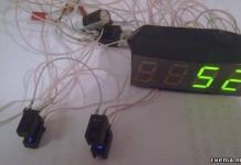
The entire installation was done in an aluminum case from a Chinese electronic transformer to power 12 volt halogen lamps.

The case turned out to be very suitable. The device cannot be distinguished directly from the factory one, although the installation of components was done on a breadboard.
Many people know how important the correct setting of the ignition timing and ignition timing regulators is for the smooth operation of the engine. An erroneous setting of the initial ignition timing by only 2-3 degrees, as well as various malfunctions of the advance regulators, will lead to a loss of engine power, overheating, increased fuel consumption and, most sadly, to a reduction in the life of the car engine.
But checking and adjusting the lead angle is a very big problem, which is not always accessible even to an experienced mechanic. A DIY strobe will help solve this problem. With their help, any motorist can check and set the ignition timing within 15 minutes, as well as check the performance of centrifugal and vacuum advance controllers.

The basis of the strobe circuit is timer devices assembled on KR1006VI1 microcircuits, which have more stable temporal characteristics, since the pulse duration and pause between pulses do not depend on the power supply voltage.
The device is connected to the high-voltage wire of the first cylinder of a gasoline engine by means of a crocodile clip. In the upper position of the SA1 switch slider, the device operates in the tachometer mode, in the lower position - in the automotive stroboscope mode.

DIY strobe circuit diagram for KR1006VI1
In the upper position of the SA1 switch slider, the DD1 timer is turned on according to the pulse generator circuit with a duration of approximately 0.5 ms and is determined mainly by the values of the resistor R4 and capacitor C2. This pulse duration is optimal and was chosen according to the following criteria. With a short pulse duration, the brightness of four LEDs in daylight may not be enough to illuminate the mark at a low engine pulley speed. With a longer pulse duration, the image of the mark will be fuzzy, “blurred” at a high engine speed.
The pulse repetition period depends on the values of resistors R5, R6 and capacitor C2, and is regulated by a variable resistor R6.
In the lower position of the SA1 switch slider, the device operates in the automotive stroboscope mode. Timer DD1 in this mode is enabled according to the single-shot pulse circuit with the same duration of 0.5 ms. The single vibrator is started by a negative voltage drop at the input of the device, which is fed through the circuit C1, R3, SA1.2 to the input of the timer DD1. Transistor VT1 amplifies the current to the required value.
The impulse current of 250 mA through the LED is too big, so the values of the resistors R11, R12 are chosen so that the impulse current through each of the HL1...HL4 LEDs at a low flash frequency does not exceed 100 mA. At a high flash frequency, the period decreases, and capacitor C6 does not have time to charge through resistor R10 to a voltage close to the voltage of the power source. Therefore, the voltage across it decreases. This leads to a decrease in the pulse current through the LEDs, which significantly increases the reliability of the device.
Diode VD1 decouples the charge and discharge circuits of capacitor C2. Resistor R3 and diode VD2 protect the timer input DD1 from high positive voltage. Timer DD1 is protected from negative voltage by resistor R3 and an internal diode. Capacitors SZ, C4 are noise suppressing. Diode VD3 protects against erroneous reversal of the power supply polarity.
Any diodes from the KD521 series can be used as diodes VD1, VD2. The VD3 diode can be replaced with any diode from the Kd212 series. The KR1006VI1 timer can be replaced with an imported analog NE555. Resistor R6 is used type SPZ-Z0a with characteristic B and a motor rotation angle of 270°. You can use a SP-I type resistor, but it has a smaller motor rotation angle - 255°.
If the radio amateur does not have a variable resistor with characteristic B at his disposal, then a variable resistor with characteristic B can be used, but in this case the scale will be reversed. If there is no variable resistor with a nominal value of 220 kOhm, you can use a variable resistor with a nominal value of 150 kOhm or 470 kOhm. In the first case, the values of resistors R4, R5 should be reduced, and the value of capacitor C2 should be increased by 1.47 times. In the second case, the values of resistors R4, R5 should be increased, and the value of capacitor C2 should be reduced by 2.14 times. The temperature and time characteristics of the device depend on the type of capacitor C2, so it is better to use capacitor C2 of type K73-17 for a voltage of 63 V. Switch SA1 - any small-sized one with two positions and two directions, for example, type P2T-1 -1 V. Capacitors C5, C6 - type K50-35, but imported ones are better, they have smaller dimensions and leakage current. Capacitor C1 is type KT-2, or another type, but it must withstand a voltage of at least 500 V. Capacitors SZ, C4 are type KMZ...KM6. Variable resistor R1 - small-sized type SP4-1. Transistor VT1 must have a current gain of less than 50 and a maximum collector current of at least 0.4 A.
As VT1, you can use a field-effect transistor KP505A (B, C). In this case, resistors R8, R9 must be excluded, and the gate of the transistor must be connected to pin 3 of the DD1 microcircuit. The wire from the clamp to the device must be shielded. Its length should not be chosen more than 35...40 cm. The shielding braid is connected to the common wire at the output of the device.
When a radio amateur develops a strobe light circuit board design with his own hands (for example, in), it should be taken into account that the input circuits of the DD1 timer should be as short as possible, since a car gasoline engine is a powerful source of interference.
Setting up a strobe light yourself
Set switch SA1 to the top position according to the diagram and calibrate the scale of variable resistor R6 using a frequency meter or, worse, an oscilloscope. As a last resort, if you do not have a frequency meter and an oscilloscope, you can calibrate the device using a digital multimeter with a capacitance meter. Pulse duration t, = 0.7 R4C2. Pause duration t2 = 0.7 (R5 + R6) C2. For ease of use, the device should be calibrated in min-1. This completes the installation of the device. There is no need to equalize currents through LEDs HL1, HL2 and HL3, HL4.
Using the device is not difficult. To check the operation of the vacuum and centrifugal ignition timing regulators of a gasoline engine, set the SA1 switch slider to the lower position. Attach the sensor to the high-voltage wire of the first cylinder of the engine, supply power to the device. Start the engine and aim the flashing light at the timing marks. If the marks are difficult to see due to dirt or metal oxides, they should be cleaned and highlighted with white paint or chalk. Set the resistance of resistor R1 so that the device stably triggers a spark only when the sensor is connected to the high voltage wire of the first cylinder of a gasoline engine.
To measure the rotation speed of the engine rotor (crankshaft), move switch SA1 to the upper position, apply power to the device and direct a beam of flashing light to the pulley of a running engine with a pre-marked mark. By rotating the motor of the variable resistor R6, make sure that the pulley with the mark appears motionless. The mark should be visible only in one place on the engine pulley. If there are two marks on the pulley, this means that the flash frequency is twice the speed of the engine shaft.
The device was tested in operation for 48 hours in tachometer mode at the minimum and maximum flash frequencies of LEDs HL1 ... HL4 from a voltage source of 16 V and showed high operational reliability.
As a relay, you can use the domestic analogue of RES-10 at 12 volts.
The circuit operates according to the following algorithm: at the moment the supply voltage is supplied from the battery, capacitor C1 begins to charge through resistor R3. Having reached the desired value, this voltage goes to the base of the transistor, which opens. After this, relay a is triggered, its contact closes and prepares the thyristor for opening. As soon as the control pulse arrives at the control electrode of the thyristor through the voltage divider on resistors R1, R2, the thyristor opens, and the capacitor begins to discharge through the LEDs. There is a short bright flash.
Then the transistor closes, opens its contact and the relay, but with a slight delay, thereby increasing the LED burning time by a fraction of a second. The circuit goes to its initial state, waiting for the next control pulse.
Thanks to this simple circuit design, the flickering of the strobe LEDs becomes brighter and the mark on the flywheel is clearly visible.

Do-it-yourself strobe, simple relay circuit
By selecting the capacitor capacity, you can vary the duration of LED burning. The higher the capacitance value, the stronger the flash, but also the longer the tag trail. With a lower capacitance value, the sharpness of the mark increases, but the brightness decreases.

Elements of the strobe circuit can be placed in the body of the LED flashlight without much difficulty. A small hole is made on the back of the flashlight and power wires at least half a meter long are passed through, at the ends of which crocodiles are soldered for ease of use. On the side of the case, a hole is also made for the shielded wire of contact X1. At the end, the screen braid is tightly wrapped with electrical tape, and a copper wire 10 cm long is soldered to the central core, which is a strobe sensor. When connected, this wire must be wound in 3-4 turns on the high-voltage wire of the first cylinder over the insulation. Be sure to wind as close to the candle as possible to avoid interference with adjacent wires.
The basis of the stroboscope circuit is the 155AG1 single vibrator integrated circuit, which is triggered by negative polarity pulses. Therefore, to form them, the control signal from the car breaker is fed to the base of the bipolar transistor VT1, which forms them. Resistors R1, R2, R3 and the zener diode VD2 are designed to limit the amplitude of the input signal coming from the ignition switch.

DIY strobe light with LEDs
Capacitance C4 and resistor R6 regulate the required duration of the pulses that are generated by the single vibrator. With the values specified as in the diagram, the duration of these pulses will be 1.5-2 ms.
Owners of carburetor cars are familiar firsthand with the difficulties of the ignition adjustment process. This is usually done by ear, which is not very convenient. Using a strobe light this process can be made easier. However, industrial devices are quite expensive, so many people make a strobe light for ignition with their own hands.
Disadvantages of industrial models
Industrial devices often have certain disadvantages that make the usefulness of the device highly questionable.
To begin with, the price for them can be quite significant. For example, modern digital models will cost a car enthusiast 1000 rubles. More functional models cost from 1700. Advanced stroboscopes cost about 5500 rubles. Needless to say, a car strobe light (made with your own hands) will cost a car enthusiast 100-200 rubles.
Often in factory devices, the manufacturer uses a particularly expensive gas-discharge lamp. The lamp has a certain lifespan, and after some time it will have to be replaced. And this in itself is tantamount to purchasing a new factory device.
Why is it worth making a strobe light yourself?
The shortcomings of factory-made and technological devices push the car enthusiast to independently manufacture this device. In addition, it is much cheaper to equip this equipment with LEDs instead of an expensive lamp. An ordinary laser pointer or flashlight is suitable as a source of diodes or a donor.
The remaining parts will also cost pennies. You don't need any special tools. The budget for the manufacturing process of a strobe light will be no more than 100 rubles.
How to make a strobe light with your own hands?
There are a huge number of schemes and options for manufacturing. However, for the most part, all projects to create this gadget are similar. Let's see what you need for assembly.

We will need a simple transistor KT315. It can be easily found in an old Soviet radio. The designation may be slightly different, but it doesn't matter. Thyristor KU112A can be easily obtained from the power supply of an old TV. You can also find small resistors there. Since we are making an LED strobe light with our own hands, we will naturally need an LED flashlight. To do this, it is better to purchase the cheapest one from China. In addition, you need to stock up on a capacitor up to 16 V, any low-frequency diode, a small 12 A relay, wires, alligators, a 0.5 m long shielded wire, as well as a small piece of copper wire.
Assembling the device
The circuit is small, but you can place it right in that same Chinese lantern. So, it is advisable to pass wires through the hole in the back of the flashlight to power the device. It is better to solder crocodiles at the ends of the wires. You need to make a hole in the side wall, if the Chinese have not already made one. The shielded wire will be routed through this hole. At the opposite end, it is necessary to insulate the braid and solder the same piece of copper wire to the main core of the wire. This will be the sensor.
Device diagram and operating principle
Once current is applied through the power wires, the capacitor will charge very quickly through the resistor. When a certain charge threshold is reached, voltage will be supplied through the resistor to the opening contact of the transistor. The relay will work here. When the relay closes, it will create a circuit of a thyristor, an LED and a capacitor. Then, through the divider, the pulse reaches the control terminal of the thyristor. Next, the thyristor will open, and the capacitor will discharge to the LEDs. As a result, the strobe light, made with your own hands, will flash brightly.

Through a resistor and a thyristor, the base terminal of the transistor is connected to the common wire. Because of this, the transistor will close and the relay will turn off. The glow time of the LEDs increases, since the contact does not break immediately. But the contact will break, and the thyristor will be de-energized. The circuit will return to its base position until a new impulse is received.
By changing the capacitance of the capacitor, you can change the glow time. If you choose a larger capacitor, the DIY LED strobe will glow brighter and longer.
Device on a chip
The main part of this simple circuit is a DD1 type microcircuit. This is the so-called one-shot 155AG1. In this circuit, it is triggered only by negative impulses. The control signal will go to the KT315 transistor, and it will generate these negative pulses. Resistors 150 K ohm, 1 k ohm, 10 k ohm, as well as the KS139 zener diode work as amplitude limiters for the incoming signal from the car ignition.
A 0.1 mF capacitor together with a resistance of 20 kOhm will set the desired duration of the pulses that will be generated by the microcircuit. With such a capacitor capacity, the pulse duration will be approximately 2 ms.
Then, from the 6th leg of the microcircuit, the pulses, which by this moment will be synchronized with the ignition of the car, will go to the base terminal of the KT 829 transistor. It is here as a key. The result is a pulsed current through the LEDs.

How is this car strobe powered? With our own hands we need to run a couple of wires to the terminals of the car battery. It is imperative to monitor the battery charge level.
If you correctly assemble this simple circuit, you will immediately be able to see how the device works. If suddenly the brightness is not enough, then this is regulated by selecting the appropriate resistance.
You can use an old or Chinese lantern as a housing for the device.
Another strobe light circuit
This LED strobe, made with your own hands according to this principle, can also be powered from a car battery. Diodes will provide protection against reverse polarity. An ordinary crocodile is used as fastener here. It needs to be attached to the high-voltage contact of the first spark plug on the engine. Next, the pulse will pass through resistors and a capacitor and arrive at the input of the trigger. By that time, this input will already be turned on by a one-shot device.
Before the pulse, the one-shot device is in normal mode. The direct trigger output is low. The inverse input is, accordingly, high. A capacitor connected with a plus to the inverse output will be charged through a resistor.
A high-level pulse triggers a monostable, which switches the trigger and serves to charge the capacitor through a resistor. After 15 ms, the capacitor will be fully charged and the trigger will switch to normal mode.
As a result, the one-shot device will respond to this with a synchronous sequence of rectangular pulses with a duration of approximately 15 ms. The duration can be adjusted by replacing the resistor and capacitor.

The pulses of the second microcircuit are up to 1.5 ms. During this period, transistors are opened, which represent an electronic switch. Current then flows through the LEDs. A strobe light for a car works on this principle (whether it was made with your own hands or not does not matter - both devices shine the same way).
The current passing through the LEDs is much greater than the rated current. But, since the flashes are short-lived, the LEDs will not fail. The brightness will be enough to use this useful device even during the daytime.

This strobe light can be assembled with your own hands in the housing of the same long-suffering flashlight.
How to operate the device?
By assembling the device according to one of the given diagrams, you can simply and easily, and most importantly, accurately adjust the ignition on carburetor engines, check the correct operation of spark plugs and coils, and control the operation of the advance angle regulators.
To set the ignition as correctly as possible, it is usually assumed that the mixture is ignited a couple of degrees before the piston reaches the highest point. This angle is called the "lead angle". As the crankshaft speed increases, the angle should also increase. So, this angle is set at idle, and then it is necessary to check the correct setting in all operating modes of the unit.
Setting the ignition
We start and warm up the engine. Now we power our LED strobe and connect the sensor. Now you need to point the device at the mark on the timing case and find the mark on the flywheel. If the moment is broken, then the marks will be quite far from each other. By rotating the timing case, ensure that the marks match. When you have found this position, lock the distributor.

Then it's time to rev up. The marks will diverge, but this is a completely normal situation. This is how the ignition is set up using a strobe light.
So, we found out how to make a LED strobe with your own hands.
A stroboscope is a piece of equipment that is capable of continuously reproducing pulses of light. Currently, the most common is the LED stroboscope. It has found its wide application in various areas of our lives. So, for example, this device is indispensable in the construction and repair industry (illumination of houses, buildings and structures), in the advertising industry, mechanical engineering, as well as in the design of restaurant and hotel complexes, cafes, nightclubs and others.
Thanks to its fairly simple design, an LED strobe can be easily made with your own hands. To do this, you only need a circuit diagram, a microcontroller, a protective device, as well as sensors, depending on the functional purpose of the device.
This car strobe light is quite powerful and can provide power to a number of LEDs. In order to assemble the device, you should buy a timer on the NE555 chip and a field-effect transistor. The most suitable transistors may be IRFZ44, IRF3205, KP812B1 and a number of others.

The desired device is quite compact and powerful. In addition, you can adjust the frequency of LED flashes. Due to the fact that a small voltage drop occurs at the junction, it is best to use a Schottky diode. Also, it is necessary to create the required tightness of the plastic case in which the board is located. In this case, synthetic silicone will be indispensable.

The field-effect transistor, as a rule, overheats during prolonged operation, so it should be installed on a heat sink. The above circuit can power LEDs whose voltage does not exceed 12 volts. Otherwise, the wiring will burn out.
A fairly large number of car enthusiasts and professionals make homemade strobe lights, since this procedure practically does not require any special knowledge and skills. In order to make a strobe light with your own hands and at the same time comply with all the requirements and preferences, you need to carefully approach the choice of LEDs. At the present time, LED devices are the most popular, since their service life, as well as the brightness of the glow, significantly exceed any other types of emitters.


