Somehow recently, on the Internet, I came across one circuit of a very simple power supply with the ability to adjust the voltage. It was possible to regulate the voltage from 1 Volt to 36 Volts, depending on the output voltage on the secondary winding of the transformer.
Take a close look at the LM317T in the circuit itself! The third leg (3) of the microcircuit clings to the capacitor C1, that is, the third leg is the INPUT, and the second leg (2) clings to the capacitor C2 and a 200 Ohm resistor and is the OUTPUT.
With the help of a transformer from a mains voltage of 220 volts, we get 25 volts, no more. Less is possible, more is not. Then we straighten the whole thing with a diode bridge and smooth out the ripples with the help of capacitor C1. All this is described in detail in the article how to get a constant voltage from an alternating voltage. And here is our most important trump card in the power supply - a highly stable voltage regulator chip LM317T. At the time of this writing, the price of this microcircuit was around 14 rubles. Even cheaper than a loaf of white bread.
Description of the microcircuit
LM317T is a voltage regulator. If the transformer produces up to 27-28 volts on the secondary winding, then we can easily regulate the voltage from 1.2 to 37 volts, but I would not raise the bar for more than 25 volts at the output of the transformer.
The microcircuit can be executed in the TO-220 package:

or in D2 Pack

It can pass a maximum current of 1.5 amps through itself, which is enough to power your electronic gadgets without a voltage drop. That is, we can give out a voltage of 36 Volts at a load current of up to 1.5 Amperes, and at the same time, our microcircuit will still give out 36 Volts as well - this, of course, ideally. In reality, fractions of a volt will drop, which is not very critical. With a large current in the load, it is more expedient to put this microcircuit on a radiator.
In order to assemble the circuit, we will also need a 6.8 Kilo-ohm variable resistor, maybe even 10 Ki-ohm, as well as a 200 Ohm fixed resistor, preferably from 1 watt. Well, at the output we put a capacitor of 100 microfarads. Absolutely simple scheme!
Assembly in hardware
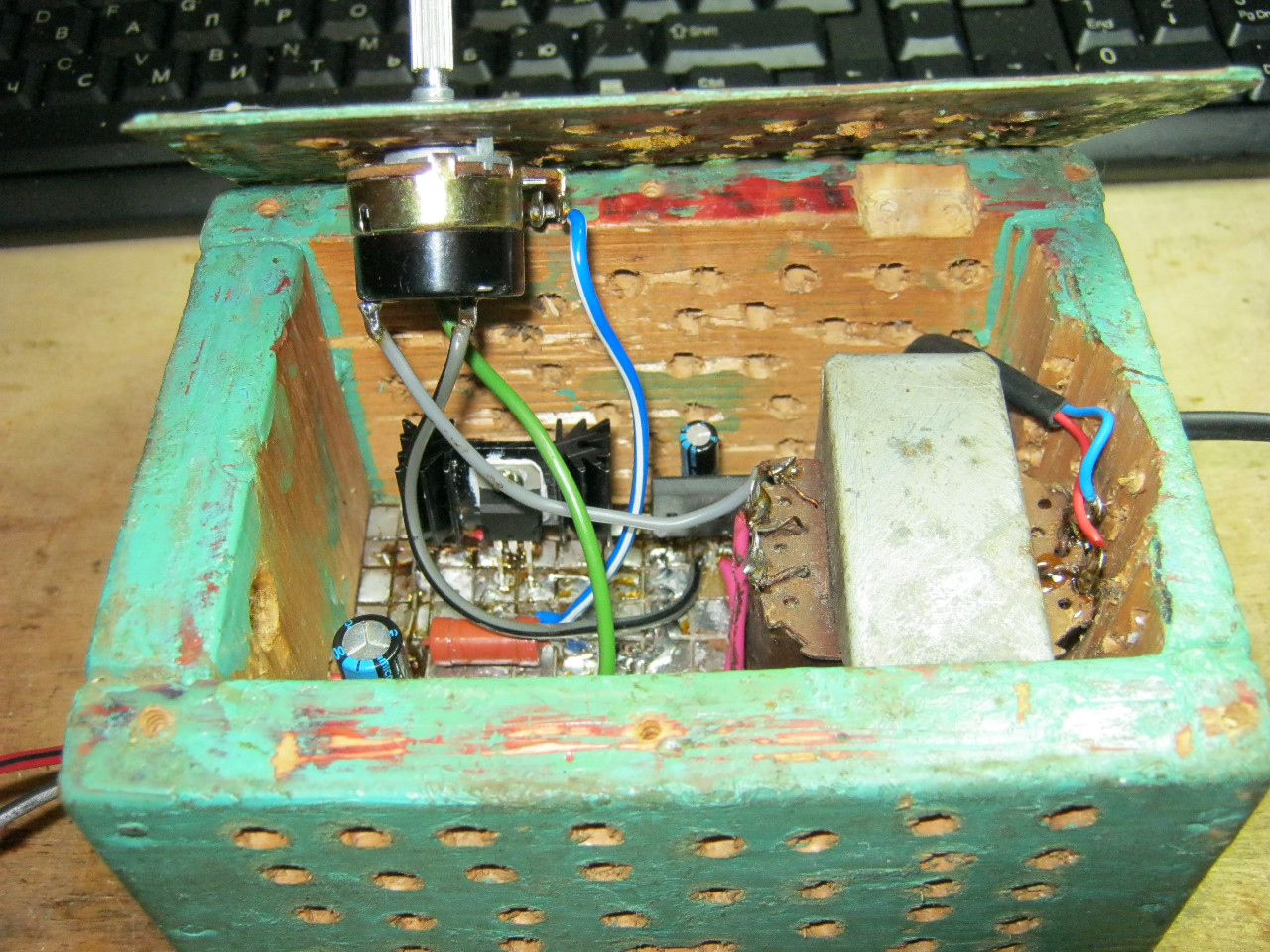
Previously, I had a very bad power supply still on transistors. I thought why not redo it? Here is the result ;-)

Here we see the GBU606 imported diode bridge. It is designed for current up to 6 amperes, which is more than enough for our power supply, since it will deliver a maximum of 1.5 amperes to the load. I put the LM-ku on the radiator using KPT-8 paste to improve heat transfer. Well, everything else, I think, is familiar to you.

And here is the antediluvian transformer, which gives me a voltage of 12 volts on the secondary winding.

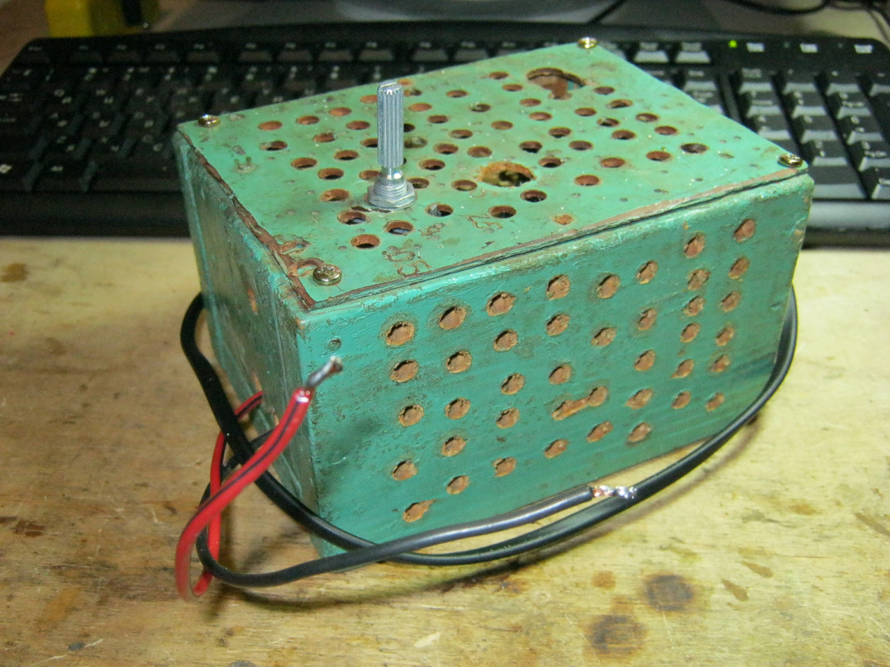
We carefully pack all this into the case and remove the wires.
So what do you think? ;-)
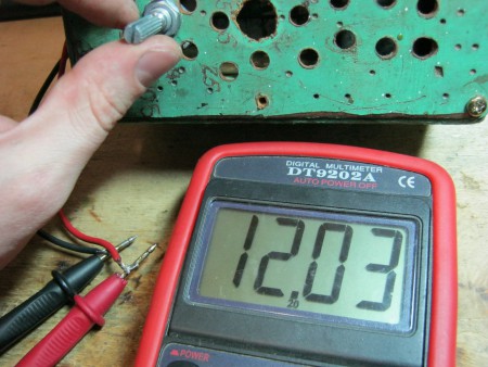
The minimum voltage I got was 1.25 Volts, and the maximum voltage was 15 Volts.


I put any voltage, in this case the most common 12 Volts and 5 Volts

Everything works with a bang!
This power supply is very convenient for adjusting the speed of a mini drill, which is used for drilling boards.

Analogues on Aliexpress
By the way, on Ali you can immediately find a ready-made set of this block without a transformer.

Too lazy to collect? You can take a ready-made 5 Ampere for less than $ 2:

You can view by this link.
If 5 Amperes is not enough, then you can look at 8 Amperes. It will be enough even for the most seasoned electronics engineer:

The master, whose device description is in the first part, having set himself the goal of making an adjustable power supply, did not complicate his business and simply used boards that were idle. The second option involves the use of even more common material - an adjustment was added to the conventional unit, perhaps this is a very promising solution in terms of simplicity, despite the fact that the necessary characteristics will not be lost and even the most experienced radio amateur can implement the idea with his own hands. As a bonus, two more options for very simple schemes with all the detailed explanations for beginners. So there are 4 options for you to choose from.
We will tell you how to make an adjustable power supply from an unnecessary computer board. The master took the computer board and sawed out the block that feeds the RAM.
This is how he looks.
Let's decide which parts need to be taken, which ones are not, in order to cut off what is needed so that all the components of the power supply are on the board. Usually, a pulse block for supplying current to a computer consists of a microcircuit, a PWM controller, key transistors, an output inductor and an output capacitor, an input capacitor. For some reason, there is also an input choke on the board. Left him too. Key transistors - maybe two, three. There is a seat for 3 transistors, but it is not used in the circuit.
The PWM controller chip itself may look like this. Here she is under a magnifying glass.

It may look like a square with small leads on all sides. This is a typical PWM controller on a laptop board.

It looks like a switching power supply on a video card.

The power supply for the processor looks exactly the same. We see a PWM controller and several processor power channels. 3 transistors in this case. Throttle and capacitor. This is one channel.
Three transistors, inductor, capacitor - the second channel. 3 channel. And two more channels for other purposes.
You know what a PWM controller looks like, look at its marking under a magnifying glass, search the Internet for a datasheet, download a pdf file and look at the diagram so as not to confuse anything.
In the diagram we see a PWM controller, but the conclusions are marked along the edges, numbered.

transistors are labeled. This is a choke. This is an output capacitor and an input capacitor. The input voltage ranges from 1.5 to 19 volts, but the voltage supply to the PWM controller should be from 5 volts to 12 volts. That is, it may turn out that a separate power supply is required to power the PWM controller. All wiring, resistors and capacitors, do not be alarmed. You don't need to know. Everything is on the board, you do not assemble a PWM controller, but use a ready-made one. You only need to know 2 resistors - they set the output voltage.
resistor divider. Its whole essence is to reduce the signal from the output to about 1 volt and apply feedback to the input of the PWM controller. In short, by changing the value of the resistors, we can adjust the output voltage. In the case shown, instead of the feedback resistor, the master put a 10 kilo-ohm tuning resistor. This proved to be sufficient to regulate the output voltage from 1 volt to about 12 volts. Unfortunately, this is not possible on all PWM controllers. For example, on our controllers for processors and video cards, in order to be able to adjust the voltage, the possibility of overclocking, the output voltage is supplied programmatically via a multi-channel bus. You can change the output voltage of such a PWM controller only with jumpers.

So, knowing what the PWM controller looks like, the elements that are needed, we can already cut out the power supply. But you need to do this carefully, since there are tracks around the PWM controller that you may need. For example, you can see - the track goes from the base of the transistor to the PWM controller. It was difficult to save it, I had to carefully cut out the board.
Using the tester in continuity mode and focusing on the circuit, I soldered the wires. Also using the tester, I found the 6th output of the PWM controller and the feedback resistors rang from it. The resistor was rfb, it was soldered out and instead of it, a 10 kilo-ohm trimming resistor was soldered from the output to regulate the output voltage, I also found out by calling that the power of the PWM controller is directly connected to the input power line. This means that it will not be possible to apply more than 12 volts to the input, so as not to burn the PWM controller.
Let's see how the power supply looks like in operation
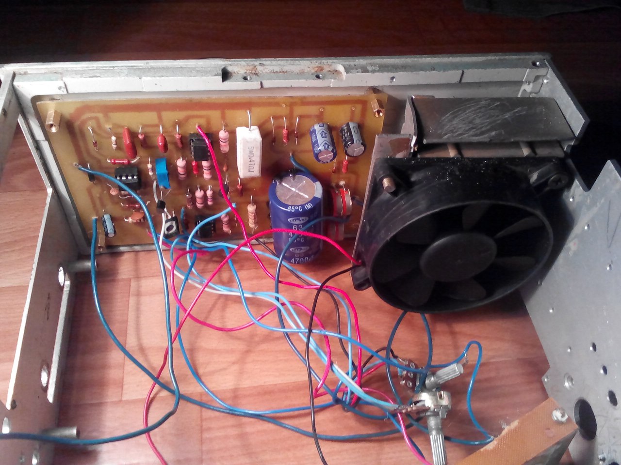
Soldered the plug for the input voltage, voltage indicator and output wires. We connect an external power supply of 12 volts. The indicator lights up. Already set to 9.2 volts. Let's try to adjust the power supply with a screwdriver.

It's time to check out what the power supply is capable of. I took a wooden block and a homemade wire resistor made of nichrome wire. Its resistance is low and, together with the tester probes, is 1.7 ohms. We turn on the multimeter in ammeter mode, connect it in series with the resistor. See what happens - the resistor glows red, the output voltage barely changes, and the current is about 4 amps.

Previously, the master has already made similar power supplies. One is cut out by hand from the laptop board.

This is the so-called duty voltage. Two sources for 3.3 volts and 5 volts. Made him a case on a 3d printer. You can also see an article where I made a similar adjustable power supply, also cut it out of a laptop board (https://electro-repair.livejournal.com/3645.html). This is also a PWM RAM power controller.
How to make a regulating PSU from a regular one, from a printer
We will talk about the canon printer power supply, inkjet. They are left unused for a lot of people. This is essentially a separate device, the printer is held on by a latch.
Its characteristics: 24 volts, 0.7 amperes.

I needed a power supply for a homemade drill. It's just right for the power. But there is one caveat - if you connect it like that, we get only 7 volts at the output. Triple output, connector and we get only 7 volts. How to get 24 volts?
How to get 24 volts without disassembling the block?
Well, the simplest is to close the plus with an average output and get 24 volts.
Let's try to do it. We connect the power supply to the network 220. We take the device and try to measure it. Connect and see the output of 7 volts.
It does not have a central connector. If we take and connect to two at the same time, we see a voltage of 24 volts. This is the easiest way to make sure that this power supply, without disassembling, gives out 24 volts.
A homemade regulator is needed so that the voltage can be regulated within certain limits. 10 volts to max. This is easy to do. What is needed for this? First, open the power supply itself. It is usually glued on. How to open it so as not to damage the case. You don't have to poke or poke anything. We take a piece of wood more massive or there is a rubber mallet. We put it on a hard surface and peel along the seam. The glue comes off. Then they sounded good on all sides. Miraculously, the glue comes off and everything opens up. Inside we see the power supply.

We'll get paid. Such power supplies are easy to convert to the desired voltage and can also be made adjustable. On the reverse side, if we turn it over, there is an adjustable zener diode tl431. On the other hand, we will see the middle contact goes to the base of the q51 transistor.


If we apply voltage, then this transistor opens and 2.5 volts appear on the resistive divider, which are necessary for the operation of the zener diode. And the output appears 24 volts. This is the easiest option. How to start it, you can still - is to throw out the transistor q51 and put a jumper instead of the resistor r 57 and that's it. When we turn it on, the output is always 24 volts continuously.
How to make an adjustment?
You can change the voltage, make it 12 volts. But in particular the master, it is not necessary. It needs to be adjustable. How to do? We discard this transistor and instead of a 57 by 38 kilo-ohm resistor we put an adjustable one. There is an old Soviet one for 3.3 kilo-ohms. You can put from 4.7 to 10, which is. Only the minimum voltage to which it can lower it depends on this resistor. 3.3 is very low and not needed. The motors are planned to be supplied at 24 volts. And just from 10 volts to 24 is normal. Who needs a different voltage, you can use a large resistance trimmer.
Let's go, let's drink. We take a soldering iron, hair dryer. Soldered the transistor and resistor.

Soldered a variable resistor and try to turn it on. I applied 220 volts, we see 7 volts on our device and we begin to rotate the variable resistor. The voltage has risen to 24 volts and smoothly rotate, it drops - 17-15-14, that is, it drops to 7 volts. In particular, it is installed at 3.3 room. And our change turned out to be quite successful. That is, for purposes from 7 to 24 volts, voltage regulation is quite acceptable.

Such an option turned out. Installed a variable resistor. The handle turned out to be an adjustable power supply - quite convenient.
Video channel "Tekhnar".
It is easy to find such power supplies in China. I came across an interesting store that sells used power supplies from various printers, laptops and netbooks. They disassemble and sell the boards themselves, fully serviceable for different voltages and currents. The biggest plus is that they dismantle branded equipment and all power supplies are of high quality, with good details, all have filters.
Photos - different power supplies, cost a penny, almost a freebie.
Simple block with adjustment
A simple version of a home-made device for powering devices with regulation. The scheme is popular, it is distributed on the Internet and has shown its effectiveness. But there are also limitations, which are shown on the video along with all the instructions for making a regulated power supply.


Homemade regulated block on one transistor
What is the simplest regulated power supply you can make yourself? This can be done on the lm317 chip. She already with herself is almost a power supply. On it, you can make both a voltage-adjustable power supply and a flow. This video tutorial shows a device with voltage regulation. The master found a simple scheme. Input voltage maximum 40 volts. Output from 1.2 to 37 volts. Maximum output current 1.5 amps. 
Without a heat sink, without a radiator, the maximum power can be only 1 watt. And with a 10 watt heatsink. List of radio components. 
Let's start assembling 


Connect an electronic load to the output of the device. Let's see how well it holds current. Set to the minimum. 7.7 volts, 30 milliamps.
 Everything is regulated. We set 3 volts and add current. On the power supply, we will set the restrictions only more. Move the toggle switch to the top position. Now 0.5 amps. The microcircuit began to warm up. Nothing to do without a heat sink. I found some kind of plate, not for long, but enough. Let's try again. There is a drawdown. But the block works. Voltage regulation is in progress. We can insert a credit for this scheme.
Radioblog video. Solderer video blog.
Every radio amateur, whether he is a teapot or even a professional, should have a sedate and important power supply on the edge of the table. I currently have two power supplies on my desk. One delivers a maximum of 15 Volts and 1 Amp (black arrow), and the other 30 Volts, 5 Amps (right):
Well, there is also a self-made power supply:

I think you often saw them in my experiments, which I showed in various articles.
I bought factory power supplies a long time ago, so they cost me inexpensively. But, at the present time, when this article is being written, the dollar is already breaking through the mark of 70 rubles. Crisis, his mother, has everyone and everything.
Okay, something went wrong ... So what am I talking about? Oh yes! I think not everyone's pockets are bursting with money ... Then why don't we assemble a simple and reliable power supply circuit with our little hands, which will be no worse than a purchased block? Actually, our reader did just that. I dug up a schematic and assembled the power supply myself:

It turned out very even nothing! So, further on his behalf…
First of all, let's figure out what this power supply is good for:
- the output voltage can be adjusted in the range from 0 to 30 volts
- you can set some current limit up to 3 Amperes, after which the block goes into protection (a very convenient function, whoever used it knows).
– very low level of ripple (DC output of the power supply is not much different from DC batteries and accumulators)
– protection against overload and incorrect connection
- on the power supply by means of a short circuit (short circuit) of the “crocodiles”, the maximum allowable current is set. Those. current limit, which you set with a variable resistor on an ammeter. Therefore overloads are not terrible. The indicator (LED) will work, indicating that the set current level is exceeded.
So, now about everything in order. The scheme has been circulating on the Internet for a long time (click on the image, it will open in a new window in full screen):

The numbers in circles are the contacts to which you need to solder the wires that will go to the radio elements.
Designation of circles in the diagram:
- 1 and 2 to the transformer.
- 3 (+) and 4 (-) DC output.
- 5, 10 and 12 on P1.
- 6, 11 and 13 on P2.
- 7 (K), 8 (B), 9 (E) to transistor Q4.
Inputs 1 and 2 are supplied with an alternating voltage of 24 Volts from the mains transformer. The transformer must be of decent size so that it can deliver up to 3 Amperes to the load into a light one. You can buy it, or you can wind it).
Diodes D1 ... D4 are connected in a diode bridge. You can take diodes 1N5401 ... 1N5408 or some others that can withstand direct current up to 3 Amperes and above. You can also use a ready-made diode bridge, which would also withstand direct current up to 3 Amperes and above. I used the KD213 tablet diodes:

Chips U1,U2,U3 are operational amplifiers. Here is their pinout (pinout). View from above:

On the eighth output, “NC” is written, which indicates that this output does not need to be hooked anywhere. Neither a minus nor a plus of food. In the circuit, conclusions 1 and 5 also do not cling anywhere.
Transistor Q1 brand BC547 or BC548. Below is its pinout:

Transistor Q2 take better Soviet, brand KT961A

Don't forget to put it on the radiator.
Transistor Q3 brand BC557 or BC327

Transistor Q4 must be KT827!

Here is his pinout:

I didn’t redraw the circuit, so there are elements that can be confusing - these are variable resistors. Since the power supply circuit is Bulgarian, their variable resistors are designated as follows:
We have it like this:

I even pointed out how to find out its conclusions using the rotation of the column (twist).
Well, actually, the list of elements:
R1 = 2.2 kOhm 1W
R2 = 82 ohm 1/4W
R3 = 220 ohm 1/4W
R4 = 4.7 kOhm 1/4W
R5, R6, R13, R20, R21 = 10 kΩ 1/4W
R7 = 0.47 ohm 5W
R8, R11 = 27 kOhm 1/4W
R9, R19 = 2.2 kOhm 1/4W
R10 = 270 kOhm 1/4W
R12, R18 = 56kΩ 1/4W
R14 = 1.5 kOhm 1/4W
R15, R16 = 1 kΩ 1/4W
R17 = 33 ohm 1/4W
R22 = 3.9 kOhm 1/4W
RV1 = 100K multi-turn trimmer
P1, P2 = 10KOhm linear potentiometer
C1 = 3300uF/50V electrolytic
C2, C3 = 47uF/50V electrolytic
C4 = 100nF
C5 = 200nF
C6 = 100pF ceramic
C7 = 10uF/50V electrolytic
C8 = 330pF ceramic
C9 = 100pF ceramic
D1, D2, D3, D4 = 1N5401…1N5408
D5, D6 = 1N4148
D7, D8 = 5.6V zener diodes
D9, D10 = 1N4148
D11 = 1N4001 diode 1A
Q1 = BC548 or BC547
Q2 = KT961A
Q3 = BC557 or BC327
Q4 = KT 827A
U1, U2, U3 = TL081, operational amplifier
D12 = LED
Now I will tell you how I collected it. The transformer has already taken ready from the amplifier. The voltage at its outputs was about 22 volts. Then he began to prepare the case for my PSU (power supply)

pickled


laundered the toner

drilled holes:

I soldered the cribs for the op amps (operational amplifiers) and all other radio elements, except for two powerful transistors (they will lie on the radiator) and variable resistors:

And this is what the board looks like with the full installation:

We prepare a place for a scarf in our case:

We attach a radiator to the case:

Do not forget about the cooler that will cool our transistors:
Well, after locksmith work, I got a very pretty power supply. So what do you think?

I took the description of the work, the signet and the list of radio elements at the end of the article.
Well, if anyone is too lazy to bother, then you can always buy a similar kit of this scheme for a penny on Aliexpress at this link


How to make a full-fledged power supply yourself with an adjustable voltage range of 2.5-24 volts, but it’s very simple, everyone can repeat without amateur radio experience behind them.
We will make it from an old computer power supply, TX or ATX, it doesn’t matter, fortunately, over the years of the PC Era, each house has already accumulated enough old computer hardware and the PSU is probably also there, so the cost of homemade products will be insignificant, and for some masters it is equal to zero rubles .
I got to remake this is the AT block.

The more powerful you use the PSU, the better the result, my donor is only 250W with 10 amps on the + 12v bus, but in fact, with a load of only 4 A, it can no longer cope, there is a complete drawdown of the output voltage.
See what is written on the case.

Therefore, see for yourself what current you plan to receive from your regulated PSU, such a donor potential and lay it right away.
There are many options for improving a standard computer PSU, but all of them are based on a change in the binding of the IC chip - TL494CN (its analogues are DBL494, KA7500, IR3M02, A494, MB3759, M1114EU, MPC494C, etc.).

Fig No. 0 Pinout of the TL494CN chip and analogues.
Let's see some options execution of computer power supply circuits, perhaps one of them will turn out to be yours and it will become much easier to deal with the strapping.
Scheme No. 1.
Let's get to work.
First you need to disassemble the PSU case, unscrew the four bolts, remove the cover and look inside.

We are looking for a microcircuit from the list above on the board, if there is none, then you can look for a refinement option on the Internet for your IC.
In my case, the KA7500 chip was found on the board, which means that we can begin to study the strapping and the location of the parts we do not need that need to be removed.

For ease of use, first completely unscrew the entire board and remove it from the case.

In the photo, the power connector is 220v.
Disconnect the power and the fan, solder or bite out the output wires so as not to interfere with our understanding of the circuit, leave only the necessary ones, one yellow (+ 12v), black (common) and green * (start ON) if there is one.

My AT unit does not have a green wire, so it starts up immediately when plugged into a power outlet. If the ATX unit, then it should have a green wire, it must be soldered to the "common", and if you want to make a separate power button on the case, then simply put the switch in the gap of this wire.

Now you need to look at how many volts the output large capacitors cost, if less than 30v is written on them, then you need to replace them with similar ones, only with an operating voltage of at least 30 volts.

In the photo - black capacitors as a replacement option for blue.
This is done because our modified unit will not produce +12 volts, but up to +24 volts, and without replacement, the capacitors will simply explode during the first test at 24v, after a few minutes of operation. When choosing a new electrolyte, it is not advisable to reduce the capacity, it is always recommended to increase it.
The most important part of the job.
We will remove all unnecessary in the IC494 harness, and solder other parts denominations, so that the result is such a harness (Fig. No. 1).

Rice. No. 1 Change in the binding of the IC 494 microcircuit (revision scheme).
We will need only these legs of the microcircuit No. 1, 2, 3, 4, 15 and 16, do not pay attention to the rest.

Rice. No. 2 Refinement option using the example of scheme No. 1
Decoding of designations.

Should be done like this, we find leg No. 1 (where there is a dot on the case) of the microcircuit and study what is attached to it, all circuits must be removed, disconnected. Depending on how you have tracks in a particular modification of the board and soldered parts, the best option for refinement is selected, it can be soldering and lifting one leg of the part (breaking the chain) or it will be easier to cut the track with a knife. Having decided on the action plan, we begin the process of rework according to the refinement scheme.


In the photo - replacing the resistors with the desired value.

In the photo - by raising the legs of unnecessary parts, we break the chains.
Some resistors that are already soldered into the piping circuit may be suitable without replacing them, for example, we need to put a resistor at R=2.7k connected to "common", but there is already R=3k connected to "common", this suits us perfectly and we leave it there unchanged (example in Fig. No. 2, green resistors do not change).


On the picture- cut tracks and added new jumpers, write down the old denominations with a marker, you may need to restore everything back.
Thus, we view and redo all the circuits on the six legs of the microcircuit.
This was the most difficult item in the alteration.
We make voltage and current regulators.

We take variable resistors of 22k (voltage regulator) and 330Ω (current regulator), solder two 15cm wires to them, solder the other ends to the board according to the diagram (Fig. No. 1). Installed on the front panel.
Voltage and current control.
For control, we need a voltmeter (0-30v) and an ammeter (0-6A).

These devices can be purchased in Chinese online stores at the best price, my voltmeter cost me only 60 rubles with delivery. (Voltmeter: )

I used my own ammeter, from the old stocks of the USSR.
IMPORTANT- inside the device there is a Current resistor (Current sensor), which we need according to the scheme (Fig. No. 1), therefore, if you use an ammeter, you do not need to install an additional Current resistor, you need to install it without an ammeter. Usually R Current is made home-made, a wire D = 0.5-0.6 mm is wound on a 2-watt MLT resistance, turn to turn for the entire length, solder the ends to the resistance leads, that's all.
Everyone will make the body of the device for themselves.
You can leave completely metal by cutting holes for regulators and control devices. I used laminate cutoffs, they are easier to drill and cut.


