Conductor resistance. Resistivity
Ohm's law is the most important in electrical engineering. That is why electricians say: “Whoever does not know Ohm’s Law should sit at home.” According to this law, current is directly proportional to voltage and inversely proportional to resistance (I = U / R), where R is a coefficient that relates voltage and current. The unit of measurement for voltage is Volt, resistance is Ohm, current is Ampere.
To show how Ohm's Law works, let's look at a simple electrical circuit. The circuit is a resistor, which is also a load. A voltmeter is used to record the voltage across it. For load current - ammeter. When the switch is closed, current flows through the load. Let's see how well Ohm's Law is observed. The current in the circuit is equal to: circuit voltage 2 Volts and circuit resistance 2 Ohms (I = 2 V / 2 Ohms = 1 A). The ammeter shows this much. The resistor is a load with a resistance of 2 ohms. When we close switch S1, current flows through the load. Using an ammeter we measure the current in the circuit. Using a voltmeter, measure the voltage at the load terminals. The current in the circuit is: 2 Volts / 2 Ohms = 1 A. As you can see, this is observed.
Now let's figure out what needs to be done to increase the current in the circuit. First, increase the voltage. Let's make the battery not 2 V, but 12 V. The voltmeter will show 12 V. What will the ammeter show? 12 V/ 2 Ohm = 6 A. That is, by increasing the voltage across the load by 6 times, we obtained an increase in current strength by 6 times.
Let's consider another way to increase the current in a circuit. You can reduce the resistance - instead of a 2 Ohm load, take 1 Ohm. What we get: 2 Volts / 1 Ohm = 2 A. That is, by reducing the load resistance by 2 times, we increased the current by 2 times.
In order to easily remember the formula of Ohm's Law, they came up with the Ohm triangle:
How can you determine the current using this triangle? I = U / R. Everything looks quite clear. Using a triangle, you can also write formulas derived from Ohm's Law: R = U / I; U = I * R. The main thing to remember is that the voltage is at the vertex of the triangle.
In the 18th century, when the law was discovered, atomic physics was in its infancy. Therefore, Georg Ohm believed that the conductor was something similar to a pipe in which a liquid flows. Only liquid in the form of electric current.
At the same time, he discovered a pattern that the resistance of a conductor becomes greater as its length increases and less as its diameter increases. Based on this, Georg Ohm derived the formula: R = p * l / S, where p is a certain coefficient multiplied by the length of the conductor and divided by the cross-sectional area. This coefficient was called resistivity, which characterizes the ability to create an obstacle to the flow of electric current, and depends on what material the conductor is made of. Moreover, the greater the resistivity, the greater the resistance of the conductor. To increase the resistance, it is necessary to increase the length of the conductor, or reduce its diameter, or select a material with a higher value of this parameter. Specifically, for copper the resistivity is 0.017 (Ohm * mm2/m).
Conductors
Let's look at what types of conductors there are. Today, the most common conductor is copper. Due to its low resistivity and high resistance to oxidation, with fairly low fragility, this conductor is increasingly being used in electrical applications. Gradually, the copper conductor is replacing the aluminum one. Copper is used in the production of wires (cores in cables) and in the manufacture of electrical products.
The second most commonly used material is aluminum. It is often used in older wiring that is being replaced by copper. Also used in the production of wires and electrical products.
The next material is iron. It has a resistivity much greater than copper and aluminum (6 times more than copper and 4 times more than aluminum). Therefore, as a rule, it is not used in the production of wires. But it is used in the manufacture of shields and tires, which, due to their large cross-section, have low resistance. Just like a fastener.
Gold is not used in electrical applications because it is quite expensive. Due to its low resistivity and high oxidation protection, it is used in space technology.
Brass is not used in electrical applications.
Tin and lead are commonly used in alloying as solder. They are not used as conductors for the manufacture of any devices.
Silver is most often used in military equipment for high-frequency devices. Rarely used in electrical applications.
Tungsten is used in incandescent lamps. Due to the fact that it does not collapse when high temperatures, it is used as filaments for lamps.
used in heating devices, as it has a high resistivity with a large cross-section. A small amount of its length is needed to make a heating element.
Coal and graphite are used in electric brushes in electric motors.
Conductors are used to pass current through themselves. In this case, the current does useful work.
Dielectrics
Dielectrics have great value specific resistance, which is much higher in comparison with conductors.
Porcelain is used, as a rule, in the manufacture of insulators. Glass is also used to produce insulators.
Ebonite is most often used in transformers. It is used to make the frame of the coils on which the wire is wound.
Also often used as dielectrics different types plastics Dielectrics include the material from which the insulating tape is made.
The material from which the insulation in the wires is made is also a dielectric.
The main purpose of a dielectric is to protect people from electric shock and to insulate current-carrying conductors among themselves.
Overclocking the power supply.
The author is not responsible for the failure of any components resulting from overclocking. By using these materials for any purpose, the end user assumes all responsibility. The site materials are presented "as is"."
Introduction.
I started this experiment with frequency due to the lack of power in the power supply.
When the computer was purchased, its power was quite sufficient for this configuration:
AMD Duron 750Mhz / RAM DIMM 128 mb / PC Partner KT133 / HDD Samsung 20Gb / S3 Trio 3D/2X 8Mb AGP

For example, two diagrams: 
Frequency f for this circuit it turned out to be 57 kHz.

And for this frequency f equal to 40 kHz.
Practice.
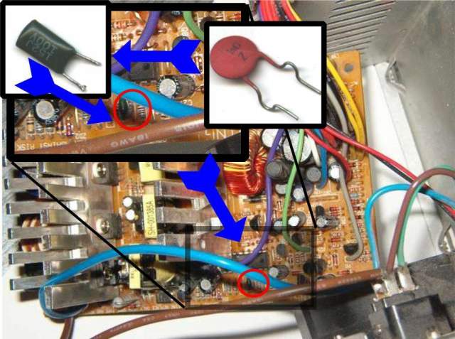
The frequency can be changed by replacing the capacitor C or/and resistor R to a different denomination.
It would be correct to install a capacitor with a smaller capacitance, and replace the resistor with series-connected ones constant resistor and variable type SP5 with flexible leads.

Then, decreasing its resistance, measure the voltage until the voltage reaches 5.0 volts. Then solder a constant resistor in place of the variable one, rounding the value up.
I took a more dangerous path - I sharply changed the frequency by soldering in a capacitor of smaller capacity.
I had:
R 1 =12kOm
C 1 =1.5nF
According to the formula we get
f=61.1 kHz
After replacing the capacitor

R 2 =12kOm
C 2 =1.0nF
f
=91.6 kHz
According to the formula:

the frequency increased by 50% and the power increased accordingly.
If we do not change R, then the formula simplifies:

Or if we don’t change C, then the formula is:

Trace the capacitor and resistor connected to pins 5 and 6 of the microcircuit. and replace the capacitor with a capacitor with a smaller capacity.


Result
After overclocking the power supply, the voltage became exactly 5.00 (the multimeter can sometimes show 5.01, which is most likely an error), almost without reacting to the tasks being performed - with a heavy load on the +12 volt bus ( simultaneous operation two CDs and two screws) - the voltage on the +5V bus may briefly decrease 4.98.
The key transistors began to heat up more. Those. If before the radiator was slightly warm, now it is very warm, but not hot. The radiator with rectifier half-bridges did not heat up any more. The transformer also does not heat up. From 09/18/2004 to this day (01/15/05) there are no questions about the power supply. On at the moment following configuration:
Links
- PARAMETERS OF THE MOST COMMON POWER TRANSISTORS USED IN PUSH-CYCLE UPS CIRCUITS MANUFACTURED FOREIGN.
- Capacitors. (Note: C = 0.77 ۰ Nom ۰SQRT(0.001۰f), where Nom is the rated capacitance of the capacitor.)
Rennie's comments: The fact that you increased the frequency, you increased the number of sawtooth pulses over a certain period of time, and as a result, the frequency with which power instabilities are monitored increased, since power instabilities are monitored more often, the pulses for closing and opening of transistors in a half-bridge switch occur at double frequency . Your transistors have characteristics, specifically their speed: By increasing the frequency, you have thereby reduced the size of the dead zone. Since you say that the transistors do not heat up, it means they are in that frequency range, which means everything seems to be fine here. But there are also pitfalls. Do you have an electrical circuit diagram in front of you? I’ll explain it to you now using the diagram. There in the circuit, look where the key transistors are, diodes are connected to the collector and emitter. They serve to dissolve the residual charge in the transistors and transfer the charge to the other arm (to the capacitor). Now, if these comrades have a low switching speed, through currents are possible - this is a direct breakdown of your transistors. Perhaps this will cause them to heat up. Now further, this is not the case, the point is that after the direct current that passed through the diode. It has inertia and when a reverse current appears: for some time the value of its resistance is not restored and therefore they are characterized not by the frequency of operation, but by the recovery time of the parameters. If this time is longer than possible, then you will experience partial through currents, which is why surges in both voltage and current are possible. In the secondary it’s not so scary, but in the power department it’s just fucked up: to put it mildly. So let's continue. In the secondary circuit, these switchings are not desirable, namely: There, Schottky diodes are used for stabilization, so at 12 volts they are supported with a voltage of -5 volts (approx. I have silicon ones at 12 volts), so at 12 volts that If only they (Schottky diodes) could be used with a voltage of -5 volts. (Due to the low reverse voltage, it is impossible to simply put Schottky diodes on the 12 volt bus, which is why they are distorted this way). But silicon diodes have more losses than Schottky diodes and the reaction is less, unless they are one of the fast-recovery diodes. So, if the frequency is high, then the Schottky diodes have almost the same effect as in the power section + the inertia of the winding at -5 volts relative to +12 volts makes it impossible to use Schottky diodes, so an increase in frequency can eventually lead to failure of them. I'm considering the general case. So let's move on. Next is another joke, finally connected directly with the feedback circuit. When you create negative feedback, you have such a thing as the resonant frequency of this feedback loop. If you reach resonance, then your entire scheme will be screwed. Sorry for the rude expression. Because this PWM chip controls everything and requires its operation in mode. And finally, a “dark horse” ;) Do you understand what I mean? It's a transformer, so this bitch also has a resonant frequency. So this crap is not a standardized part, the transformer winding product is manufactured individually in each case - for this simple reason you do not know the characteristics of it. What if you introduce your frequency into resonance? You burn your trance and you can safely throw away the power supply. Externally, two absolutely identical transformers can have completely different parameters. Well, the fact is that by choosing the wrong frequency you could easily burn out the power supply. Under all other conditions, how can you still increase the power of the power supply? We increase the power of the power supply. First of all, we need to understand what power is. The formula is extremely simple - current to voltage. The voltage in the power part is 310 volts constant. So, we cannot influence the voltage in any way. We have only one trans. We can only increase the current. The amount of current is dictated to us by two things - transistors in the half-bridge and buffer capacitors. The conductors are larger, the transistors are more powerful, so you need to increase the capacitance rating and change the transistors to ones that have a higher current in the collector-emitter circuit or just a collector current, if you don’t mind, you can plug in 1000 uF there and not strain yourself with calculations. So in this circuit we did everything we could, here, in principle, nothing more can be done, except perhaps taking into account the voltage and current of the base of these new transistors. If the transformer is small, this will not help. You also need to regulate such crap as the voltage and current at which your transistors will open and close. Now it seems like everything is here. Let's go to the secondary circuit. Now we have a lot of current at the output windings....... We need to slightly correct our filtering, stabilization and rectification circuits. For this, we take, depending on the implementation of our power supply, and change the diode assemblies first of all, so that we can ensure the flow of our current. In principle, everything else can be left as is. That's all, it seems, well, at the moment there should be a margin of safety. The point here is that the technique is impulsive - this is its bad side. Here almost everything is built on the frequency response and phase response, on t reaction.: that’s all
The article will talk about how to increase the current in the charger circuit, in the power supply, transformer, in the generator, in the USB ports of the computer without changing the voltage.
What is current strength?
Electric current is the ordered movement of charged particles inside a conductor with the obligatory presence of a closed circuit.
The appearance of current is due to the movement of electrons and free ions that have a positive charge.
As they move, charged particles can heat the conductor and have a chemical effect on its composition. In addition, the current can influence neighboring currents and magnetized bodies.
Current strength is an electrical parameter that is a scalar quantity. Formula:
I=q/t, where I is current, t is time, and q is charge.
It is also worth knowing Ohm's law, according to which current is directly proportional to U (voltage) and inversely proportional to R (resistance).
Current strength is of two types - positive and negative.
Below we will consider what this parameter depends on, how to increase the current strength in the circuit, in the generator, in the power supply and in the transformer.
What does current strength depend on?
To increase I in a circuit, it is important to understand what factors can influence this parameter. Here we can highlight the dependence on:
- Resistance. The smaller the parameter R (Ohm), the higher the current in the circuit.
- Voltages. Using the same Ohm's law, we can conclude that as U increases, the current strength also increases.
- Magnetic field strength. The larger it is, the higher the voltage.
- Number of coil turns. The greater this indicator, the greater U and, accordingly, the higher I.
- The power of the force that is transmitted to the rotor.
- Diameter of conductors. The smaller it is, the higher the risk of heating and burning out the supply wire.
- Power supply designs.
- The diameter of the stator and armature wires, the number of ampere-turns.
- Generator parameters - operating current, voltage, frequency and speed.
How to increase the current in a circuit?
There are situations when it is necessary to increase I, which flows in the circuit, but it is important to understand that measures need to be taken; this can be done using special devices.
Let's look at how to increase the current using simple devices.
To complete the work you will need an ammeter.
Option 1.
According to Ohm's law, current is equal to voltage (U) divided by resistance (R). The simplest way to increase force I, which suggests itself, is to increase the voltage that is supplied to the input of the circuit, or to reduce the resistance. In this case, I will increase in direct proportion to U.
For example, when connecting a 20 Ohm circuit to a power source with U = 3 Volts, the current value will be 0.15 A.
If you add another 3V power source to the circuit, the total value of U can be increased to 6 Volts. Accordingly, the current will also double and reach a limit of 0.3 Amperes.
The power supplies must be connected in series, that is, the plus of one element is connected to the minus of the first.
To obtain the required voltage, it is enough to connect several power sources into one group.
In everyday life, sources of constant U, combined into one group, are called batteries.

Despite the obviousness of the formula, practical results may differ from theoretical calculations, which is due to additional factors - heating of the conductor, its cross-section, the material used, and so on.
As a result, R changes towards an increase, which leads to a decrease in force I.
Increasing the load in the electrical circuit can cause overheating of the conductors, burnout, or even a fire.
That is why it is important to be careful when operating devices and take into account their power when choosing a cross-section.
The value of I can be increased in another way by reducing the resistance. For example, if the input voltage is 3 Volts and R is 30 Ohms, then a current of 0.1 Ampere passes through the circuit.
If you reduce the resistance to 15 Ohms, the current strength, on the contrary, will double and reach 0.2 Amperes. The load is reduced to almost zero during a short circuit near the power source, in this case I increases to the maximum possible value (taking into account the power of the product).
Resistance can be further reduced by cooling the wire. This effect of superconductivity has long been known and is actively used in practice.
To increase the current in a circuit, electronic devices are often used, for example, current transformers (as in welders). The strength of variable I in this case increases with decreasing frequency.
If in a chain AC there is active resistance, I increases as the capacitor capacitance increases and the inductance of the coil decreases.
In a situation where the load is purely capacitive in nature, the current increases with increasing frequency. If the circuit includes inductors, the force I will increase simultaneously with the decrease in frequency.
Option 2.
To increase the current strength, you can focus on another formula, which looks like this:
I = U*S/(ρ*l). Here we only know three parameters:
- S - wire cross-section;
- l is its length;
- ρ is the electrical resistivity of the conductor.
To increase the current, assemble a chain containing a current source, a consumer and wires.
The role of the current source will be performed by a rectifier, which allows you to regulate the EMF.
Connect the chain to the source, and the tester to the consumer (pre-set the device to measure current). Increase the EMF and monitor the indicators on the device.

As noted above, as U increases, it is possible to increase the current. A similar experiment can be done for resistance.
To do this, find out what material the wires are made of and install products that have lower resistivity. If you cannot find other conductors, shorten the ones already installed.
Another way is to increase the cross-section, for which it is worth mounting similar conductors parallel to the installed wires. In this case, the cross-sectional area of the wire increases and the current increases.
If we shorten the conductors, the parameter we are interested in (I) will increase. If desired, options for increasing the current can be combined. For example, if the conductors in the circuit are shortened by 50% and U is raised by 300%, then the force I will increase 9 times.
How to increase the current in the power supply?
On the Internet you can often come across the question of how to increase I in the power supply without changing the voltage. Let's look at the main options.
Situation No. 1.
A 12 Volt power supply operates with a current of 0.5 Amperes. How to raise I to its maximum value? To do this, a transistor is placed in parallel with the power supply. In addition, a resistor and stabilizer are installed at the input.
When the voltage across the resistance drops to the required value, the transistor opens, and the rest of the current flows not through the stabilizer, but through the transistor.
The latter, by the way, must be selected according to the rated current and a radiator installed.
In addition, the following options are possible:
- Increase the power of all elements of the device. Install a stabilizer, a diode bridge and a higher power transformer.
- If there is current protection, reduce the value of the resistor in the control circuit.
Situation No. 2.
There is a power supply for U = 220-240 Volts (at the input), and at the output a constant U = 12 Volts and I = 5 Amperes. The task is to increase the current to 10 Amps. In this case, the power supply should remain approximately the same dimensions and not overheat.
Here, to increase the output power, it is necessary to use another transformer, which is converted to 12 Volts and 10 Amps. Otherwise, the product will have to be rewound yourself.

In the absence of the necessary experience, it is better not to take risks, because there is a high probability of a short circuit or burnout of expensive circuit elements.
The transformer will have to be replaced with a larger product, and the damper chain located on the DRAIN of the key will also have to be recalculated.
The next point is replacement electrolytic capacitor, because when choosing a capacity you need to focus on the power of the device. So, for 1 W of power there are 1-2 microfarads.

After such a modification, the device will heat up more, so installing a fan is not necessary.
How to increase the current in the charger?
When using chargers, you may notice that chargers for a tablet, phone or laptop have a number of differences. In addition, the speed at which devices are charged may also vary.
Here, a lot depends on whether an original or non-original device is used.
To measure the current that flows to your tablet or phone from the charger, you can use not only an ammeter, but also the Ampere app.
Using the software, it is possible to determine the charging and discharging speed of the battery, as well as its condition. The application is free to use. The only drawback is advertising (the paid version does not have it).

The main problem with charging batteries is the low current of the charger, which is why the time to gain capacity is too long. In practice, the current flowing in the circuit directly depends on the power of the charger, as well as other parameters - cable length, thickness and resistance.
Using the Ampere application, you can see at what current the device is charged, and also check whether the product can charge at a higher speed.
To use the capabilities of the application, just download it, install and run it.

After this, the phone, tablet or other device is connected to the charger. That's all - all that remains is to pay attention to the current and voltage parameters.
In addition, you will have access to information about the battery type, U level, battery condition, as well as temperature conditions. You can also see the maximum and minimum I that occur during the cycle.
If you have several chargers at your disposal, you can run the program and try charging each of them. Based on the test results, it is easier to select a charger that provides the maximum current. The higher this parameter is, the faster the device will charge.
Current measurement isn't the only thing Ampere can do. With its help, you can check how much I is consumed in standby mode or when turning on various games (applications).

For example, after turning off the display brightness, deactivating GPS or data transfer, it is easy to notice a decrease in load. Against this background, it is easier to conclude which options drain the battery the most.
What else is worth noting? All manufacturers recommend charging devices with “native” chargers that produce a certain current.
But during operation, there are situations when you have to charge your phone or tablet with other chargers that have more power. As a result, the charging speed may be higher. But not always.
Few people know, but some manufacturers limit the maximum current that the device’s battery can accept.
For example, a Samsung Galaxy Alpha device comes with a 1.35 Ampere charger.
When connecting a 2-amp charger, nothing changes - the charging speed remains the same. This is due to a limitation set by the manufacturer. A similar test was carried out with a number of other phones, which only confirmed the guess.
Taking into account the above, we can conclude that non-native chargers are unlikely to cause harm to the battery, but can sometimes help with faster charging.
Let's consider another situation. When charging a device via a USB connector, the battery gains capacity more slowly than when charging the device from a conventional charger.
This is due to the limitation of the current that a USB port can supply (no more than 0.5 Ampere for USB 2.0). When using USB3.0, the current increases to 0.9 Ampere.
In addition, there is a special utility that allows the “troika” to pass a larger I through itself.
For devices like Apple the program is called ASUS Ai Charger, and for other devices it is called ASUS USB Charger Plus.

How to increase the current in a transformer?
Another question that worries electronics enthusiasts is how to increase the current strength in relation to a transformer.
Here are the following options:
- Install a second transformer;
- Increase the diameter of the conductor. The main thing is that the cross-section of the “iron” allows it.
- Raise U;
- Increase the cross-section of the core;
- If the transformer operates through a rectifier device, it is worth using a product with a voltage multiplier. In this case, U increases, and with it the load current also increases;
- Buy a new transformer with a suitable current;
- Replace the core with a ferromagnetic version of the product (if possible).
A transformer has a pair of windings (primary and secondary). Many output parameters depend on the wire cross-section and the number of turns. For example, there are X turns on the high side and 2X on the other side.

This means that the voltage on the secondary winding will be lower, as will the power. The output parameter also depends on the efficiency of the transformer. If it is less than 100%, U and the current in the secondary circuit decrease.
Taking into account the above, the following conclusions can be drawn:
- The power of the transformer depends on the width of the permanent magnet.
- To increase the current in the transformer, a decrease in R load is required.
- The current (A) depends on the diameter of the winding and the power of the device.
- In case of rewinding, it is recommended to use thicker wire. In this case, the wire mass ratio on the primary and secondary windings is approximately identical. If you wind 0.2 kg of iron on the primary winding and 0.5 kg on the secondary winding, the primary will burn out.
How to increase the current in the generator?
The current in the generator directly depends on the load resistance parameter. The lower this parameter, the higher the current.
If I is higher than the nominal parameter, this indicates the presence of an emergency mode - frequency reduction, generator overheating and other problems.
For such cases, protection or disconnection of the device (part of the load) must be provided.
In addition, with increased resistance, the voltage decreases, and U increases at the generator output.
To maintain the parameter at an optimal level, regulation of the excitation current is provided. In this case, an increase in the excitation current leads to an increase in the generator voltage.
The network frequency must be at the same level (constant).
Let's look at an example. IN car generator it is necessary to increase the current from 80 to 90 Amperes.
To solve this problem, you need to disassemble the generator, separate the winding and solder the lead to it, followed by connecting the diode bridge.

In addition, the diode bridge itself is changed to a part with higher performance.
After this, you need to remove the winding and a piece of insulation in the place where the wire is to be soldered.
If there is a faulty generator, the lead is bitten off from it, after which the legs of the same thickness are built up using copper wire.
After soldering, the joint is insulated with heat shrink.


The next step is to buy an 8-diode bridge. Finding it is a very difficult task, but you have to try.

Before installation, it is advisable to check the product for serviceability (if the part is used, a breakdown of one or more diodes is possible).
After installing the bridge, attach the capacitor, and then a 14.5-volt voltage regulator.

You can purchase a pair of regulators - 14.5 (German) and 14 Volts (domestic).
Now the rivets are drilled out, the legs are unsoldered and the tablets are separated. Next, the tablet is soldered to a domestic regulator, which is fixed with screws.
All that remains is to solder the domestic “pill” to the foreign regulator and assemble the generator.


Occasionally need to increase force happening in an electrical circuit current. This article will discuss the basic methods of increasing current without the use of difficult devices.
You will need
- Ammeter
Instructions
1. According to Ohm's law for continuous current electrical circuits: U = IR, where: U is the magnitude of the voltage supplied to the electrical circuit, R is the total resistance of the electrical circuit, I is the magnitude of the current flowing through the electrical circuit, to determine the current strength, it is necessary to divide the voltage supplied to circuit to its total resistance. I=U/RAccordingly, in order to increase the current strength, it is possible to increase the voltage supplied to the input of the electrical circuit or reduce its resistance. The current strength will increase if the voltage is increased. The increase in current will be proportional to the increase in voltage. Let's say, if a circuit with a resistance of 10 Ohms was connected to a standard battery with a voltage of 1.5 Volts, then the current flowing through it was: 1.5/10 = 0.15 A (Ampere). When another 1.5 V battery is connected to this circuit, the total voltage will become 3 V, and the current flowing through the electrical circuit will increase to 0.3 A. The connection is made in stages, that is, the plus of one battery is connected to the minus of the other. Thus, by combining a sufficient number of power sources in steps, it is possible to obtain the required voltage and ensure the flow of current of the required strength. Several voltage sources combined into one circuit are called a battery of elements. In everyday life, such designs are usually called “batteries” (even if the power source consists of each of one element). However, in practice, the increase in current strength may differ slightly from the calculated one (proportional to the increase in voltage). This is mainly due to the additional heating of the circuit conductors, which occurs with an increase in the current passing through them. In this case, as usual, the resistance of the circuit increases, which leads to a decrease in current strength. In addition, an increase in the load on the electrical circuit can lead to its burnout or even fire. You must be extremely careful when operating electrical household appliances that can only operate at a fixed voltage.
2. If you reduce the total resistance of an electrical circuit, the current will also increase. According to Ohm's law, the increase in current will be proportional to the decrease in resistance. Say, if the voltage of the power source was 1.5 V, and the circuit resistance was 10 Ohms, then an electric current of 0.15 A passed through such a circuit. If after this the circuit resistance is halved (made equal to 5 Ohms), then the resulting along the circuit, the current will double and amount to 0.3 Amperes. An extreme case of decreasing load resistance is a short circuit, in which the load resistance is actually zero. In this case, of course, an immense current does not appear, because there is an internal resistance of the power source in the circuit. A more significant reduction in resistance can be achieved if the conductor is cooled tightly. The acquisition of high currents is based on this result of superconductivity.
3. To increase the strength of alternating current, all kinds of electronic devices are used, mainly current transformers, used, say, in welding units. The strength of the alternating current also increases as the frequency decreases (because the net result is that the energetic resistance of the circuit decreases). If there are energetic resistances in the alternating current circuit, the current will increase as the capacitance of the capacitors increases and the inductance of the coils (solenoids) decreases. If the circuit contains only capacitors (capacitors), the current will increase as the frequency increases. If the circuit consists of inductors, then the current strength will increase as the frequency of the current decreases.
According to Ohm's law, increasing current in a circuit, it is permissible if one of two conditions is fulfilled: an increase in voltage in the circuit or a decrease in its resistance. In the first case, change the source current on another, with greater electromotive force; in the second, select conductors with lower resistance.

You will need
- a regular tester and tables for determining the resistivity of substances.
Instructions
1. According to Ohm's law, on a section of the chain the force current depends on 2 quantities. It is directly proportional to the voltage in this area and inversely proportional to its resistance. Universal connectedness is described by an equation that can be easily derived from Ohm’s law I=U*S/(?*l).
2. Assemble an electrical circuit that contains a source current, wires and electricity buyer. As a source current use a rectifier with the possibility of adjusting the EMF. Connect the circuit to such a source, having previously installed a tester into it in stages for the buyer, configured to measure force current. Increasing the emf of the source current, take readings from the tester, from which it can be concluded that as the voltage increases on a section of the circuit, the force current it will increase proportionally.
3. 2nd method to increase strength current– reduction of resistance in a section of the circuit. To do this, use a special table to determine the resistivity of this section. To do this, find out in advance what material the conductors are made of. In order to increase force current, install conductors with lower resistivity. The smaller this value, the greater the force. current in this area.
4. If there are no other conductors, resize the ones that are available. Increase their cross-sectional areas, install the same conductors parallel to them. If current flows through one wire core, install several wires in parallel. By how many times the cross-sectional area of the wire increases, the current will increase by how many times. If possible, shorten the wires used. By how many times the length of the conductors decreases, by how many times the force increases current .
5. Methods for increasing strength current allowed to combine. Say, if you increase the cross-sectional area by 2 times, reduce the length of the conductors by 1.5 times, and the emf of the source current increase by 3 times, get an increase in strength current you 9 times.
Tracking shows that if a current-carrying conductor is placed in a magnetic field, it will begin to move. This means that some force is acting on it. This is the Ampere force. Since its appearance requires the presence of a conductor, a magnetic field and an electric current, the metamorphosis of the parameters of these quantities will allow the Ampere force to increase.

You will need
- – conductor;
- – current source;
- – magnet (continuous or electro).
Instructions
1. A conductor carrying current in a magnetic field is acted upon by a force equal to the product of the magnetic induction of the magnetic field B, the strength of the current flowing through the conductor I, its length l and the sine of the angle? between the vector of magnetic field induction and the direction of current in the conductor F=B?I?l?sin(?).
2. If the angle between the lines of magnetic induction and the direction of the current in the conductor is acute or obtuse, orient the conductor or field in such a way that this angle becomes right, that is, there should be a right angle of 90? between the magnetic induction vector and the current. Then sin(?)=1, and this is the highest value for this function.
3. Enlarge force Ampere, acting on the conductor, increasing the value of the magnetic induction of the field in which it is placed. To do this, take a stronger magnet. Use an electromagnet, one that allows you to get a magnetic field of different intensities. Increase the current in its winding, and the inductance of the magnetic field will begin to increase. Strength Ampere will increase in proportion to the magnetic induction of the magnetic field, say, increasing it 2 times, you will also get an increase in strength by 2 times.
4. Strength Ampere depends on the current strength in the conductor. Connect the conductor to a current source with variable emf. Enlarge force current in the conductor by increasing the voltage at the current source, or replace the conductor with another one, with the same geometric dimensions, but with lower resistivity. Let's say replace an aluminum conductor with a copper one. Moreover, it must have the same cross-sectional area and length. Increased strength Ampere will be directly proportional to the increase in current strength in the conductor.
5. To increase the force value Ampere increase the length of the conductor, the one in the magnetic field. At the same time, strictly consider that the current strength will decrease proportionally; therefore, a primitive lengthening will not give results; at the same time, bring the value of the current strength in the conductor to the initial value, increasing the voltage at the source.
Video on the topic
Video on the topic
Voltage and current are two basic quantities in electricity. In addition to them, a number of other quantities are also distinguished: charge, magnetic field strength, electric field strength, magnetic induction and others. In everyday work, a practicing electrician or electronics engineer most often has to operate with voltage and current - Volts and Amperes. In this article we will talk specifically about tension, what it is and how to work with it.
Determination of a physical quantity
Voltage is the potential difference between two points and characterizes the work done by the electric field to transfer charge from the first point to the second. Voltage is measured in Volts. This means that tension can only be present between two points in space. Therefore, it is impossible to measure voltage at one point.
Potential is denoted by the letter "F", and voltage by the letter "U". If expressed in terms of potential difference, the voltage is equal to:
If expressed in terms of work, then:
where A is work, q is charge.
Voltage measurement
Voltage is measured using a voltmeter. The voltmeter probes are connected to two voltage points between which we are interested, or to the terminals of a part whose voltage drop we want to measure. Moreover, any connection to the circuit can affect its operation. This means that when you add a load in parallel to an element, the current in the circuit changes and the voltage on the element changes according to Ohm’s law.
Conclusion:
The voltmeter must have the highest possible input resistance so that when it is connected, the final resistance in the measured area remains practically unchanged. The resistance of the voltmeter should tend to infinity, and the higher it is, the greater the reliability of the readings.

The measurement accuracy (accuracy class) is influenced by a number of parameters. For pointer instruments, this includes the accuracy of calibration of the measuring scale, design features pointer suspension, quality and integrity of the electromagnetic coil, condition of the return springs, accuracy of shunt selection, etc.
For digital devices - mainly the accuracy of the selection of resistors in the measuring voltage divider, the ADC capacity (the larger, the more accurate), the quality of the measuring probes.

To measure DC voltage using a digital device (for example,), as a rule, it does not matter whether the probes are connected correctly to the circuit being measured. If you connect a positive probe to a point with a more negative potential than the point to which the negative probe is connected, a “-” sign will appear on the display in front of the measurement result.

But if you measure with a pointer instrument, you need to be careful. If the probes are connected incorrectly, the arrow will begin to deviate towards zero and will hit the limiter. When measuring voltages close to the measurement limit or more, it may jam or bend, after which there is no need to talk about the accuracy and further operation of this device.
For most measurements in everyday life and in electronics at the amateur level, a voltmeter built into multimeters such as DT-830 and the like is sufficient.
The larger the measured values, the lower the requirements for accuracy, because if you measure fractions of a volt and you have an error of 0.1V, this will significantly distort the picture, and if you measure hundreds or thousands of volts, then an error of 5 volts will not play a significant role.
What to do if the voltage is not suitable for powering the load
To power each specific device or apparatus, you need to supply a voltage of a certain value, but it happens that the power source you have is not suitable and produces low or too high voltage. This problem is being solved in different ways, depending on the required power, voltage and current.
How to reduce voltage with resistance?
The resistance limits the current and as it flows, the voltage across the resistance (current-limiting resistor) drops. This method allows you to lower the voltage to power low-power devices with consumption currents of tens, maximum hundreds of milliamps.
An example of such power supply is the inclusion of an LED in the network DC 12 (for example, a car’s on-board network up to 14.7 Volts). Then, if the LED is designed to be powered from 3.3 V, with a current of 20 mA, you need a resistor R:
R=(14.7-3.3)/0.02)= 570 Ohm
But resistors differ in maximum power dissipation:
P=(14.7-3.3)*0.02=0.228 W
The closest higher value is a 0.25 W resistor.
It is the dissipated power that imposes a limitation on this method of power supply; it usually does not exceed 5-10 W. It turns out that if you need to extinguish a large voltage or power a more powerful load in this way, you will have to install several resistors because The power of one is not enough and it can be distributed among several.
The method of reducing voltage with a resistor works in both DC and AC circuits.
Flaw - output voltage is not stabilized by anything and as the current increases and decreases, it changes in proportion to the resistor value.
How to reduce AC voltage with a choke or capacitor?
If we are talking only about alternating current, then reactance can be used. Reactance exists only in alternating current circuits; this is due to the peculiarities of energy storage in capacitors and inductors and the laws of switching.
The inductor and capacitor in alternating current can be used as a ballast resistor.
The reactance of the inductor (and any inductive element) depends on the frequency of the alternating current (for a household electrical network 50 Hz) and inductance, it is calculated by the formula:
![]()
where ω is the angular frequency in rad/s, L is the inductance, 2pi is necessary to convert the angular frequency to normal, f is the voltage frequency in Hz.
The reactance of a capacitor depends on its capacitance (the lower C, the greater the resistance) and the frequency of the current in the circuit (the higher the frequency, the lower the resistance). It can be calculated like this:
![]()
An example use of inductive reactance is power supply fluorescent lamps lighting, DRL lamps and HPS. The choke limits the current through the lamp; in LL and HPS lamps it is used in conjunction with a starter or a pulse ignition device (starting relay) to form a high voltage surge that turns on the lamp. This is due to the nature and operating principle of such lamps.
A capacitor is used to power low-power devices; it is installed in series with the powered circuit. Such a power supply is called a “transformerless power supply with a ballast (quenching) capacitor.”
It is very often found as a current limiter for charging batteries (for example, lead batteries) in portable flashlights and low-power radios. The disadvantages of such a scheme are obvious - there is no control of the battery charge level, they boil over, undercharge, and voltage instability.

How to lower and stabilize DC voltage
To achieve a stable output voltage, you can use parametric and linear stabilizers. They are often made on domestic microcircuits such as KREN or foreign ones such as L78xx, L79xx.


The LM317 linear converter allows you to stabilize any voltage value, it is adjustable up to 37V, you can make a simple adjustable power supply based on it.

If you need to slightly reduce the voltage and stabilize it, the described ICs will not be suitable. For them to work there must be a difference of about 2V or more. LDO (low dropout) stabilizers were created for this purpose. Their difference is that to stabilize the output voltage, it is necessary that the input voltage exceed it by an amount of 1V. An example of such a stabilizer is AMS1117, available in versions from 1.2 to 5V, the 5 and 3.3V versions are most often used, for example, and much more.
The design of all the above-described series-type linear step-down stabilizers has a significant drawback - low efficiency. The greater the difference between the input and output voltage, the lower it is. It simply “burns” excess voltage, converting it into heat, and the energy loss is equal to:
Ploss = (Uin-Uout)*I
The AMTECH company produces PWM analogues of L78xx type converters; they operate on the principle of pulse width modulation and their efficiency is always more than 90%.

They simply turn the voltage on and off with a frequency of up to 300 kHz (ripple is minimal). And the current voltage is stabilized at the required level. And the connection circuit is similar to linear analogues.

How to increase constant voltage?
To increase the voltage, pulse voltage converters are produced. They can be switched on using either a boost or buck scheme or a buck-boost scheme. Let's look at a few representatives:

2. Board based on LM2577, works to increase and decrease the output voltage.

3. Converter board based on FP6291, suitable for assembling a 5 V power source, such as a powerbank. By adjusting the resistor values, it can be adjusted to other voltages, like any other similar converter - you need to adjust the feedback circuits.


Here everything is labeled on the board - pads for soldering the input - IN and output - OUT voltages. The boards can have output voltage regulation, and in some cases, current limiting, which allows you to make a simple and effective laboratory power supply. Most converters, both linear and pulsed, have short-circuit protection.
How to increase AC voltage?
To adjust AC voltage, two main methods are used:
1. Autotransformer;
2. Transformer.
Autotransformer- This is a choke with one winding. The winding has a tap from a certain number of turns, so by connecting between one of the ends of the winding and the tap, at the ends of the winding you get an increased voltage as many times as the total number of turns and the number of turns before the tap.
The industry produces LATRs - laboratory autotransformers, special electromechanical devices to regulate voltage. They have found very wide application in development electronic devices and repair of power supplies. Adjustment is achieved through a sliding brush contact to which the powered device is connected.

The disadvantage of such devices is the lack of galvanic isolation. This means that high voltage can easily be present at the output terminals, hence the risk of electric shock.

Transformer- This classic way changes in voltage. There is galvanic isolation from the network, which increases the safety of such installations. The voltage on the secondary winding depends on the voltage on the primary winding and the transformation ratio.
Uvt=Ufirst*Ktr

A separate species is . They operate at high frequencies of tens and hundreds of kHz. Used in the vast majority of switching power supplies, for example:
Charger for your smartphone;
Laptop power supply;
Computer power supply.

Due to operation at high frequencies, the weight and size indicators are reduced, they are several times less than that of network (50/60 Hz) transformers, the number of turns on the windings and, as a result, the price. Go to impulse blocks power supply made it possible to reduce the size and weight of all modern electronics, reduce its consumption by increasing efficiency (in pulse circuits 70-98%).
Electronic transformers are often found in stores; a 220V mains voltage is supplied to their input, and at the output, for example, 12 V high-frequency alternating voltage; for use in a load that is powered by direct current, it is necessary to additionally install high-speed diodes at the output.

Inside there is a pulse transformer, transistor switches, a driver, or a self-oscillator circuit, as shown below.

Advantages: simplicity of the circuit, galvanic isolation and small size.
Disadvantages - most models that are on sale have current feedback, which means that without a load with a minimum power (indicated in the specifications of a particular device), it simply will not turn on. Some copies are already equipped with OS voltage and operate at idle without problems.
They are most often used to power 12V halogen lamps, for example suspended ceiling spotlights.
Conclusion
We covered the basics of voltage, its measurement, and adjustments. A modern element base and a range of ready-made units and converters allows us to implement any power sources with the required output characteristics. You can write a separate article about each of the methods in more detail; within this article, I tried to fit the basic information necessary to quickly select a solution that is convenient for you.


 Leo born in the year of the Rabbit")


