A section of a house is considered a finished drawing, which depicts the structure and all internal features, as well as components. On such a plan, you can see the location of various elements of the building: windows, doors, or even interior items. Such a layout will help determine in advance what is needed for arranging the premises.
Drawing of a two-story house to create a project
The main feature of such a drawing is the ability to specify the dimensions of various nuances of the structure. In order for such a layout to be effective, it is necessary to position the section plane in the correct way.
A feature of this type of document is a vertical sectional plane, which conveys accurate information about the dimensions of an element. One of the main marks in such a drawing is the indication of the distance from the ceiling to the floor:

Such information will be useful both for the workers themselves, who will receive all the necessary data and a plan for carrying out the work, and for future residents, who will be able to plan the arrangement of the building using the information transmitted by the sectional drawing.
Designing a house according to a sectional drawing
Drawing up a sectional drawing is a priority in modern construction. Such a layout is mainly influenced by the size of the future premises, as well as the number of people who will live in this building. Thus, you can get, but with many small rooms or a couple of large ones, which will provide maximum space in the room.

Creating a house project from a sectional drawing
In addition, the minimum, or storage room, is selected.
To create such a convenient layout, it is necessary to draw up a sectional drawing of the house, which will greatly simplify and reduce the cost of further work on the installation of the premises.
Having a sectional drawing for your house project, you will be able to choose the correct location of the future building on the site.
Sectional drawing for summer cottages
As a rule, it does not have much space, but with a good layout it will be enough to implement everything you need.
When drawing up a sectional drawing for a frame building, you should pay attention to where which room needs to be placed:
- sleeping quarters are best placed so that their windows look in a southeast or east direction;
- , and the entrance hall should be in the west;
- or guest rooms should be located in the southeast or south side of the house.

Drawings with the dimensions of all floors of the house
The correct location of living quarters will allow not only to get a large amount of light in the right place, but also to create the right air exchange between the rooms.
The sectional drawing will be quite thoughtful, but at the same time simple. It is simplicity that is the guarantor of the quality and ease of use of the drawing by builders or designers.
Layout of a small room according to a sectional drawing
Limited opportunities during construction do not always mean the impossibility of well equipping your living space. Even if your location is only a few square meters, and it is not possible to complete additional floors or an attic, you can still correctly distribute the space.
Unlike the design of apartment premises, it has its own characteristics: 
- It is necessary to plan the arrangement of such a dwelling quite carefully, since the heat transfer of an ordinary house is much higher than apartment buildings due to the fact that all external walls communicate with the street, and there is also no entrance and other heated general-purpose premises. Therefore, the location of the rooms in the house should be given special attention when developing drawings.
- The sectional drawing should take into account the need for a vestibule for most types of residential premises, regardless of the layout. So in the house there will be less heat loss through walls, doors and windows.
- In some cases, the drawing will need to indicate the device of the veranda. It can be either open type or glazed. If planned, then the presence of a vestibule is not mandatory.
Having made a sectional drawing for his home, the owner of the house will provide himself with comfort and coziness.
Today, durable materials are used in construction, allowing not only to build a strong building, but also to give it an aesthetically beautiful look. Thus, it is necessary to choose the right building materials. Very important design of building facades at house design especially when it comes to graduation projects.
Imagine a project that combines neat construction drawings properly embellished with gradient, fill, and even hatching. This immediately raises the level of your project. Therefore, in this lesson building facade drawing in AutoCAD).
When drawing the facade of the house, it is necessary to place its plan below. It is best to additionally use a section of the building.

According to the plan, we expose horizontal lines-rays. They must be installed in the corners of the house, at the beginning and end of window and door openings. This is how we get drawing lines that indicate walls and form window and door blocks. A section is used to orient doors and windows vertically.

If the latter is not ready, then you can start from the point indicating the height of the floor of the first floor, in this case it is more difficult to draw, since at the same time you need to work on replacing the section (calculate the heights of the points of the beginning and end of the openings ...).

After the lines denoting the top of the floor have been demolished from the section, it is also necessary to sit the lines that will become the lines of windows and doors.

If you remove the extra elements, you get window and door blocks.

The second point is tables and text on whatman paper. Drawings must be arranged in a certain sequence. Of course, there are no very strict requirements in this, but you should familiarize yourself with the main factors. You can familiarize yourself with them by looking at the finished theses or by watching the video lesson on the layout of the graduation project.
House drawing - facade and floor plan
How is the drawing of the facade of the building carried out in accordance with the current standards and rules? What are the different projections of a building called?
Let's get acquainted with the general rules for the execution of construction drawings.
In the photo - a sketch of the facade of those times when the requirements for project documentation differed from the current ones.
General provisions
The answer to the question of how to draw the facade of a building, we will begin by listing the requirements common to all construction drawings and diagrams.
Terminology
- All construction drawings are obtained by projecting a certain type of building onto a plane.
- The actual drawing of the facade of the house is its frontal projection onto a plane parallel to the facade .
- The projection of a section of a building in a longitudinal or transverse plane is, respectively, a longitudinal or transverse section.
- If a horizontal section of a building is transferred to paper, it is commonly called a plan. Depending on the level at which the cut is made, it can be a basement plan, a first floor plan, and so on.
- A top view of a site that includes a building or a group of buildings and structures is commonly called a master plan.
- Finally, no matter what object is depicted - the basement of a kindergarten, the facade of an industrial building, the facade of a cottage, the facade of a cafe or a toilet in a summer cottage - all these images have a common name: architectural and construction drawings.
Despite the spread of electronic media, the drawings must be printed on paper.
Regulations
Sections, plans and drawings of building facades must be made in a common ESKD system (unified system for design documentation). Its standards are determined by GOST 2.301-68 - GOST 2.307-68.
What exactly is regulated?
- Sheet formats for all drawings.
Important: format requirements imply certain aspect ratios of the sheet itself, and not the drawing frame.
- Scale series of images.
- Line thickness.
- The name of the image elements.
- Drawing fonts.
- Image methods on the drawings of various objects.
- Graphic designations of various materials.
The following scales can be used when drawing up master plans for objects:

In the drawings of facades and plans, of course, larger scales are also used.
A 1:1 scale can be used when transferring complex-shaped cornices and other small elements onto paper. However, this is rather an exception. Zoom scales are not used in architectural and construction drawings.
Rules for the execution of drawings
In order to correctly make drawings of house facades, floor plans and other architectural and construction schemes with your own hands, you need to adhere to fairly strict rules.
- The thickness of the main line must be the same for all details of the drawing, performed on the same scale. An exception is sectional drawings: visible contour lines can be drawn with a thin line.
- Names, headings and designations in the drawing field can be written without inclination. But the dimensions and other inscriptions on the arrows are written obliquely, with an angle relative to the base of the line of about 75 degrees.
- The total number of dimensions in the drawing should be, as common sense suggests, sufficient for construction work. In this case, duplication of the same size on different elements of the image is allowed.
- Dimensions are given in millimeters without indicating units of measurement. However, the level above the ground is indicated in meters to the third decimal place.

Traditionally, all dimensions in the drawings are indicated in millimeters. The rule is not absolute; but other units of measurement should be indicated in the notes.
Attention: it is permissible to indicate dimensions in centimeters, provided that the units of measurement are specified in the note to the drawing. And in this case, the units of measurement are not specified separately.
Features of drawings of facades
We have listed the general provisions. Are there any nuances associated specifically with the facades that interest us primarily? How to draw the facade of the building in accordance with the current rules?
- The drawing of the façade should give a clear idea of the appearance of the façade of the building (see beautiful facades of private houses), the proportions and size of individual elements.
- If the facade and the plan are on the same drawing, they are performed on the same scale and must be in projection connection. What does this mean? Only that the plan is located on the drawing under the facade.
- The facades of different sides of the building have their own names, which are indicated on the drawing. There are main, courtyard and side (end) facades.
- The drawing indicates all the structural details that will be present in a real building. For example, the main facade of the school in the drawing should be equipped with a porch, a yard facade with a fire escape; cornices, dormer windows and other seemingly trifles are drawn.
- In a technical project, it is customary to show its own shadows and the shadows falling on it on the facade. To do this, the drawing is painted with watercolors or shaded with dry grated ink.
- The facade drawing does not indicate the horizontal dimensions. However, on the one hand, at a distance of 15-20 millimeters from the contour of the facade, general height dimensions and level marks for the ground, windows and doors, plinth, eaves and ridge of the roof and the top points of pipes and ventilation are affixed.
- At the bottom of the facade, axes of expansion joints and differences in the height of the building are applied.
Before us is a drawing of the facade made in accordance with all the rules. Quite complex, I must say. It was taken from a very real building - the Bolshoi Drama Theater on the Fontanka embankment in St. Petersburg.
Conclusion
You can find more information about building drawings at the end of the article. In addition, it is useful to know that the price of the design is the project of the facade and floors of the cottage. including a complete set of drawings, starts from 10,000 rubles for standard solutions. Exclusive projects can cost ten times more. Successes in construction!
Facade drawings are an important part of the project. Plans and sections are considered other main components. For an accurate understanding of what each section of the project documentation is, and what is the difference between them, it is necessary to consider each concept separately.
Facade drawings - definition and features
A facade drawing is a graphic representation of the appearance of a building being designed from different sides, the so-called side view. It necessarily contains elevation marks and other dimensions that determine the position of the structural elements of the house, visible from the outside. Unlike color renderings of a façade, the drawing is done on a plane and does not contain perspective distortion, color or shadows.
To obtain a visual representation of the designed house, colored facades are additionally developed. Their main goal is to give the customer an idea of what the completed building looks like. Often, the general term "facades" refers to both parts of the project documentation described above. The main differences between them are:
The drawing of the facade of the house refers to the working documentation and is necessary for creating masonry drawings and developing the structural, technical and architectural part of the project;
Facades in color allow you to get an idea of the appearance and aesthetic parameters of the future building, the methods and materials of decoration, as well as its architectural features.
|
|

Drawings of facades of houses and cottages are made in accordance with design standards and rules in the same style with other parts of the documentation. This is necessary in order to make it easier to read the drawings and compare them with each other.
There are no uniform norms and standards for the development of facades in color, however, in most cases, designers and architects try to unify all the design documentation being developed. Therefore, two versions of colored facades are made - a large one for easier visualization and a regular one in a scale similar to technical drawings.
Differences between the facade drawing and the plan and section
Along with the drawings of the facades, plans and sections are other important components of the project documentation. Plans are a graphic representation of various elements and parts of a building when viewed from above. This is the main difference between the plans and facades of the house, which are carried out as a side view.
Another significant difference between the documents in question is the number. The maximum number of facade drawings is four, and many more plans are usually developed:
- general (general plan);
- floor by floor;
- masonry;
- marking (with statements of premises);
- finishing
- roofs, etc.
Most plans (except general and roofing) are developed for each floor.
The section of the house is similar to the facade in that it is also a side view. In this case, it is not the visible outer part of the building that is considered, but some of the hidden internal planes. Sections allow you to get an idea of the structure of the building and perform the same role as plans. Their number depends on the complexity of the design of the house and the detail of the project documentation. The more cuts, the more convenient and easier it is to carry out construction work.
https://infinityquest.com https://hunterae.com https://cmsdude.org https://powerpointone.com https://htmldownload.com
Today, durable materials are used in construction, allowing not only to build a strong building, but also to give it an aesthetically beautiful look. Thus, it is necessary to choose the right building materials. Very important design of building facades at house design especially when it comes to graduation projects.
Imagine a project that combines neat construction drawings properly embellished with gradient, fill, and even hatching. This immediately raises the level of your project. Therefore, in this lesson building facade drawing in AutoCAD).
When drawing the facade of the house, it is necessary to place its plan below. It is best to additionally use a section of the building.

According to the plan, we expose horizontal lines-rays. They must be installed in the corners of the house, at the beginning and end of window and door openings. This is how we get the lines of the drawing, denoting the walls and forming the window and door blocks. A section is used to orient doors and windows vertically.

If the latter is not ready, then you can start from the point indicating the height of the floor of the first floor, in this case it is more difficult to draw, since at the same time you need to work on replacing the section (calculate the heights of the points of the beginning and end of the openings ...).

After the lines denoting the top of the floor have been demolished from the section, it is also necessary to sit the lines that will become the lines of windows and doors.

If you remove the extra elements, you get window and door blocks.

The second point is tables and text on whatman paper. Drawings must be arranged in a certain sequence. Of course, there are no very strict requirements in this, but you should familiarize yourself with the main factors. You can familiarize yourself with them by looking at the finished theses or by watching the video lesson on the layout of the graduation project.
Construction drawing considers the rules for the implementation of drawings of buildings and structures.
All buildings and structures according to their functional purpose can be divided into civil, industrial, transport and agricultural.
Civil buildings are residential and public buildings: residential buildings, hotels, hostels, schools, educational institutions, various institutions, banks, theaters and cinemas, hospitals, etc.
Industrial buildings - factories and plants, industrial complexes and combines, hydro and thermal power plants, garages, warehouses, etc.
Transport facilities - bridges, overpasses, overpasses, bus stations, parking lots, etc.
Agricultural buildings - farms for keeping animals, warehouses for storing agricultural products, fertilizers, feed, buildings for storing equipment, etc.
Construction drawings are very diverse. They have much in common with engineering drawings, but also have many of their own specific features.
Construction drawings are performed according to the general rules of their rectangular projection onto the main projection planes.
The projections of the building in the drawing have their own names.
Views of the building from the back, front, right and left are called building facades. If the facade faces a street or square, such a facade is called main. The name of the facade in the drawing is given according to the alignment axes to which it is attached: "Facade in axes 1-4" or along the axis along which it is located: "Facade along axis A" (Figure 10.1).

Figure 10.1 - Facade of a residential building
View of the building from above roof plan(roofs). The roof plan and facades of the building give an idea of the shape of the building, the number of floors, the presence of balconies and loggias, the location of the entrance doors, the dimensions of the building, as well as its architectural appearance.
Information about the location of individual rooms of the building, their size, the placement of sanitary equipment, and the main building structures can be obtained from plans and sections.
Building plan called a horizontal plane cut through window and door openings.
If you mentally cut the building with a horizontal plane and cut off its upper part, and project the remaining part onto the horizontal projection plane, then the resulting image will be the plan of the building. Horizontal cutting planes are usually drawn through the windows and doors of each floor and receive the plans of the 1st, 2nd and subsequent floors, respectively. If the layout of the 2nd and subsequent floors is the same, then it is drawn 1 time and is called a typical floor plan. In an industrial building, the plan is carried out at the level of various elevations and the resulting plans are called according to these marks: “Plan for elev. +6.00” (Figure 10.2-10.3).

Figure 10.2 - An example of a floor plan

Figure 10.3 - An example of combining floor plans
cut call the image of one part of the building, mentally dissected by a vertical plane. The position of the cutting plane is shown on the building plan. The cut is called longitudinal, if the cutting plane is parallel to the longitudinal walls of the building, and transverse if the cutting plane is perpendicular to the longitudinal walls. Sometimes, to obtain a cut, not one, but several parallel cutting planes are used. In this case, the cut is called stepped(Figure 10.4).

Figure 10.4 - An example of a section of a building
The direction of the cutting plane for the section is depicted on the plan of the 1st floor as a thick open line (2s) with arrows indicating the direction of the observer's gaze. The secant plane is assigned a name, denoted by capital letters of the Russian alphabet. The same name is assigned to the cut obtained as a result of cutting the object by a cutting plane.
Plans, facades and sections of the building are called general architectural and construction drawings. Based on the general architectural and construction drawings of the building, drawings are drawn up for the production of special construction works for water supply and sewerage, heating and ventilation, gas supply and electricity supply, etc.
10.2. Design stages
Design institutes, design bureaus and research institutes take part in the design of any of the above structures
The construction of buildings and engineering structures is carried out according to approved projects and estimates for them. The project includes construction drawings necessary for the execution of works, an explanatory note and an estimate that determines the total cost of construction. The estimate defines the volumes for certain types of work, the number of building materials and products, the number of workers by profession and construction mechanisms.
Various design and engineering teams take part in the design of any structure. Design is divided into the following stages:
- Design assignment
- Feasibility study of construction
The feasibility study is compiled by the design organization in the form of project proposals, taking into account the prospects for the development of economic regions and individual industries.
- Design assignment
The design task is drawn up by the customer with the participation of the general designer on the basis of an approved feasibility study.
- Development of project documentation, containing a technical design and working drawings (design in 2 stages) or a technical design combined with working drawings (design in 1 stage).
With one-stage design, all drawings are working.
Technical project(first stage of design) with a summary estimate of the cost of construction is developed on the basis of a feasibility study and a design assignment. It aims to establish the most appropriate volumetric layout of the building, the composition and dimensions of individual rooms, the materials and structures of individual elements of buildings, as well as the total cost of construction.
The technical project includes general architectural and construction drawings: plans, facades, sections without detailed study, the general plan of the construction site (which shows existing and planned buildings and structures, landscaping - sidewalks, roads, green spaces, as well as the supply of communication systems) , an explanatory note with the rationale for the adopted space-planning and design solution and an estimate of the cost of construction.
Working drawings(second design stage) are carried out on the basis of an approved technical design.
The composition of the working drawings for the construction of the building includes general architectural and construction drawings, plans, facades, sections with detailed study of individual fragments, assemblies and parts, drawings and wiring diagrams of all structural elements - foundations, floors, walls, roofs, drawings of sanitary devices and landscaping.
10.3 Marking drawings
During the construction of buildings and structures, general construction and special works are carried out. General construction work includes a cycle of work related to the construction and decoration of the building, and special work includes the installation of water supply, sewerage, heating and ventilation, gas pipelines, electrical wiring, telephone communications, etc.
Working drawings intended for the production of a certain type of work are combined into sets by brand. In accordance with GOST 21.101-93 and GOST 21.501-93, each main set of working drawings is assigned an independent name, consisting of the initial (capital) letters of the name of a certain part of the project.
Drawing Mark maintained at all stages of design. For individual sets of working drawings, the following marks are established:
- master plan - GP;
- architectural drawings - AR;
- building structures - KS;
- architectural and construction part (combination of AR and KS brands) - AS;
- reinforced concrete structures - KZh;
- metal structures - KM;
- electric lighting - EO, etc.
The design and construction of buildings is carried out in accordance with certain norms and rules, which are set out in the official publications of the "Building Norms and Rules" (SNiP).
When designing buildings and structures, all space-planning dimensions, dimensions of structural elements and the location of coordination axes must meet the requirements of the Unified Modular Size Coordination System (EMSC), which is the basis for the unification and standardization of dimensions in construction. EMSK is a set of rules for coordinating sizes and mutual placement of space-planning and structural elements of buildings and structures, building products and equipment based on a spatial system of modular coordinates. The value of the main module is taken equal to 100 mm and is denoted by the letter M. All other enlarged and fractional modules are formed on the basis of the main module by multiplying it by integer or fractional numbers.
Enlarged modules expressed in the following dimensions: 6000, 3000, 1500, 1200, 600, 300 mm. They are conventionally designated: 60 m, 30 m, 15 m, 12 m, 6 m and 3 m. Fractional modules expressed in the following sizes: 50, 20, 10, 5, 2 and 1 mm. They are designated respectively 1/2 m, 1/5 m, 1/10 m, 1/20 m, 1/50 m and 1/100 m. sections of columns, beams, floor slabs, etc., as well as gaps, seams, etc.
10.4 Grid of coordination axes of supporting structures. Binding of load-bearing longitudinal and transverse walls to modular coordination axes
Coordination axes on the plan are drawn along the outer and inner main walls. The distance between the coordinate axes on the plan is called the pitch. There are longitudinal and transverse steps. The span is the distance between the coordination axes in the direction of the main supporting structure of the floor or cover. The span often coincides with the step. Coordination axes are applied to the drawing with thin dash-dotted lines and are indicated in circles. The diameter of circles for drawings made at a scale of 1:400 and less is taken equal to 6 mm, and for drawings at a scale of 1:200 and larger - 8¸12 mm. The numbers indicate the coordination axes along the side of the building with a large number of coordination axes, and the capital letters of the Russian alphabet indicate the coordination axes along the side with a smaller number of axes. The font size for designating the coordination axes is taken 1.5 - 2 times the size of the digits of the dimensional numbers used in the same drawing.
The binding of the bearing longitudinal and transverse walls of buildings and structures to the modular coordination axes is carried out as follows (Figures 10.1-10.4):
a) geometric axis internal walls combined with modular coordination axes;
b) an asymmetric arrangement with respect to the modular coordination axes is allowed only for stairwell walls, walls with ventilation ducts, etc.; in the walls of stairwells, the coordination axes are drawn at a distance that is a multiple of the module from the inner face of the wall facing the stairs;
c) inner edge exterior walls placed from the coordination axis at a distance equal to half the thickness of the wall;
e) it is allowed to combine the inner face outer wall with a coordinating axis.
10.5 Stroke rules for drawings. Inscriptions. Scales. Dimension. Marks for binding elements of buildings and structures in height. Product marking
The rules for the graphic design of drawings are similar to the rules for the execution of engineering drawings, taking into account some features in choosing scales, applying dimensions, sequencing drawings, etc. Stroke of construction drawings is carried out in accordance with GOST 21.501-93. The thickness of the lines when tracing the drawings of plans, sections and facades is taken depending on the accepted scale. So, for example, at a scale of 1:100, the thickness of contour lines when tracing plans and sections of buildings and structures made of stone and reinforced concrete is taken equal to 0.6-0.7 mm, and facades, window and door openings - 0.4-0.5 mm; at a scale of 1:400, the thickness of the contour lines is assumed to be 0.4 mm and 0.3 - 0.4 mm, respectively. The thickness of the contour lines when tracing the details of stone, brick and concrete elements at a scale of 1:20 is taken equal to 0.8 mm, and at a scale of 1:1 - 1 mm. On the plans of architectural and construction drawings, floors are highlighted with thicker lines, and the contours of the walls are outlined with lines somewhat thinner. In the drawings of building structures, reinforcement is also distinguished by thick lines, and the contours of the structure itself are thinner, etc.
Inscriptions on construction drawings are made in font according to GOST 2.304-81. The font size for different inscriptions is applied differently. In the main inscription: the name of the design organization, object, sheet, etc. performed with a height of 5-7 mm, other inscriptions - with a height of 3.5-5 mm; the name of the main drawings and tables is 5-7 mm high, and the secondary drawings and text instructions are 3.5-5 mm high; digital data for filling tables -2.5-3.5 mm. The designation of the coordination axes, reference and numbering marking of nodes, position numbers with a circle diameter of up to 9 mm is performed in a font size of 3.5 or 5 mm high, and with a diameter of more than 10 mm - 5 or 7 mm.
The height of dimensional numbers in drawings made on a scale of 1:100 and larger is taken equal to 3.5 mm, and for scales of 1:200 and less - 2.5 mm.
Scales on construction drawings according to GOST 21.101-79 are not marked. However, if necessary, it is allowed to indicate the scale in the main inscription according to the type 1:10, 1:100, etc., and above the image according to the type "A-A (1:50)". scale of images of plans, facades, sections, structures, etc. should be taken as minimal, taking into account the complexity of the image, but it is necessary to ensure the clarity of the image, taking into account modern methods of reproduction of drawings. The scale of images of plans, sections, facades, structures, etc. civil, industrial, agricultural, transport buildings and structures are performed in accordance with GOST 2.302-69, taking into account the requirements of GOST 21.501-93. So, for example, floor plans (except for technical ones), sections, facades, plans, ceilings, coverings, wiring diagrams of frames are drawn at a scale of 1:400, 1:200, 1:100, and with greater saturation of images - 1:50; roofing plans, floors, technical floors - on a scale of 1:1000, 1:800, 1:500, 1:200; fragments of plans, facades, plans and sections of stairs, installation diagrams of internal walls - on a scale of 1:100, 1:50; foundation plans - on a scale of 1:200, 1:100; nodes - on a scale of 1:20, 1:10, 1:5, etc.
Dimensions on construction drawings are applied in accordance with GOST 2.303-68, taking into account the requirements of the design documentation system for construction - GOST 21.105-79. Dimensions in mm on construction drawings are applied in the form of a closed chain without indicating the unit of measurement. If dimensions are given in other units, such as cm, then they are specified in the notes to the drawings. Dimension lines are limited by serifs 2–4 mm long at an angle of 45 ° to the dimension line with an inclination to the right. The thickness of the serif line is taken equal to the thickness of the solid main line adopted in this drawing. Dimension lines should protrude 1 - 3 mm beyond the extreme extension lines. The dimension number is located above the dimension line at a distance of up to 1 mm. The distance from the drawing outline to the first dimension line is assumed to be at least 10 mm. The distance between parallel dimension lines must be at least 7 mm, and from the dimension line to the circle of the coordination axis - 4 mm (Figures 10.5-10.8).

Figure 10.5 - Coordination axes: a - no more than 3; b - more than 3; c - with alphabetic and numeric axes; d - with the orientation of the coordination axes
Marks for binding elements of buildings and structures in height are indicated in meters with three decimal places after the occupied one. For a conditional zero mark, the mark of the finished floor of the first floor, denoted by 0.000, is taken. Marks above the conditional zero are indicated without a sign, and below the conditional zero - with a minus sign (-). On facades and sections, marks are placed on extension lines or contour lines. Mark mark is an arrow with a shelf. The arrow is made with main lines 2–4 mm long, drawn at an angle of 45 ° to the extension line or contour line. The mark mark may be accompanied by explanatory inscriptions. For example: Ur. n.p. - the level of the clean floor, Ur. h. – ground level (Figure 10.6).

Figure 10.6 - Applying elevation marks on the drawings of facades, sections, sections: a - conventional mark mark; b - the location of the mark and shelf; c - application of the sign; g - the same, with explanatory signs

Figure 10.7 - Restriction of dimension lines: a - serif; b - arrow, (s - thickness of the main line); in - dot

Figure 10.8 - Drawing dimension and extension lines
Typical products are marked stamps in accordance with the drawings of typical products, catalogs and standards.
The brand of products on construction drawings is applied next to the products or on the shelves of extension lines. For example, for prefabricated prefabricated buildings, the panel of the inner wall can be designated B24, and the outer wall H14, etc. (Figure 10.9).

Figure 10.9 - An example of marking products (window and door openings) in the drawing
The design and construction of buildings and structures is carried out in strict accordance with building codes and regulations (SNiP), the "Unified System for Design Documentation" (ESKD), which are collections of state standards (GOST), the "Project Documentation System for Construction" (SPDS), instructions on the composition and design of drawings, the use of which is mandatory for all design and construction organizations.
10.6 Main parts of buildings and structures
The building is a complex engineering structure, consisting of a number of interconnected structures. The vast majority of civil, industrial, transport and agricultural buildings are ground structures, the main structural elements of which are foundations, walls, lintels, frames, columns, crossbars, floors and roofs, partitions, doors, windows, stairs, etc.
By type of load transfer buildings can be frame, frameless or mixed (frame-stone or frame-panel).
frame is the main load-bearing structure in frame buildings. It is a flat or spatial system of interconnected columns and crossbars. The frame can be made of reinforced concrete and metal. The frame is called complete when the columns are located around the perimeter and inside the building and structure. The frame is called incomplete, if part of the load is taken by the columns that replace the internal walls, and part - by the load-bearing external walls.
In regions prone to strong earthquakes, to impart spatial rigidity and stability to stone and panel buildings, combined frame-stone (brick) and frame-panel systems are used, where a metal, and mostly reinforced concrete frame is located inside the masonry or in vertical and horizontal seams between panels.
Consider the main load-bearing structures of civil buildings, which are divided into underground And ground. Underground structures are bases and foundations . Base is a layer of soil on which the foundation of a building rests. Rocky soils are ideal natural foundations. If the soils are weak, representing an alternation of various layers of sand, clay, silt-peat layers, etc. saturated with water, then piles are driven into the soil to strengthen them. The length of the pile is selected so that its lower end rests on rocks or dense soils. Previously, piles were made of hardwood, but now they are mainly made of reinforced concrete. Wooden piles are used at a high level of groundwater in such a way that the pile is completely immersed in the water-saturated soil layer and does not rot.
Foundations designed to transfer and distribute the load from the building to the ground. Foundations are tape, columnar and solid. Strip foundations are laid under the bearing walls of stone, block, panel and wooden houses. Strip foundations are made of rubble concrete, concrete, baked brick, durable wood impregnated with an antiseptic, as well as prefabricated concrete and reinforced concrete blocks. Strip foundations are a structure of variable section. The lower wide part is called the sole, and the upper narrower part is called the surface. The overall dimensions of the foundation are assigned according to the calculation.
Pillar foundations are made in the form of free-standing pillars. They are used in frame buildings made of prefabricated and monolithic reinforced concrete. For weak soils and a large vertical load, solid foundations are used from a reinforced monolithic slab of calculated thickness, on which strip foundations are laid.
Foundation structures are shown on foundation plans and in sections (Figures 10.10 - 10.11).

Figure 10.10 - Images of foundation structures. Fragment of prefabricated strip foundation.

Figure 10.11 - Images of foundation structures. Fragment of the foundation under the column.
plinth called the lower part of the wall, which is, as it were, a continuation of the foundation. It rises above the ground to the level of a clean floor. The plinth is made of materials of increased strength and frost resistance, protecting the lower part of the wall from mechanical damage and atmospheric influences. Very often, the base is lined with a durable moisture-resistant material. Usually the plinth exceeds the thickness of the wall by at least 40 mm.
In the absence of sidewalks, adjacent to the basement blind area, which serves to divert atmospheric water from the walls of the building. The blind area is made of monolithic concrete or cobblestone with a 3% slope and is covered on top with waterproofing, consisting of two layers of roofing material on bituminous mastic, on top of which asphalt or cement-sand mortar is laid with or without tile lining. The width of the blind area is taken at least 500 mm.
Walls there are load-bearing, self-supporting and hinged . carriers or capital walls are called walls, on which interfloor ceilings and coatings are based. self-supporting walls are called, working only on the load from its own weight and wind load. Load-bearing and self-supporting walls rest on their own foundation or foundation beams. Mounted the walls are hung on the supporting elements of the frame. Their main role is to protect the premises from the influence of temperature and atmospheric influences.
The walls are divided into external and internal. Depending on the material of the walls and the type of construction All buildings and structures are divided into the following groups:
- Buildings with walls made of bricks, stone, small concrete blocks and local building materials (raw bricks, clay blocks, shell rocks, sandstones, rounded or torn stone in clay mortar, etc.).
- Large block buildings are made of large horizontal and vertical blocks laid out with dressing of seams.
- Large-panel buildings, erected from panels, the size in length and height in one or two rooms. The outer wall panels have window openings, while the inner wall panels have door openings. Usually, at the factories, panels are produced with glazed window frames.
- Volumetric block buildings are assembled from three-dimensional blocks one or two rooms in size with longitudinal and transverse walls and a ceiling. Such buildings have great spatial rigidity.
- Buildings with walls made of monolithic concrete according to the method of erection, they are divided into buildings erected in a sliding formwork and buildings erected in a three-dimensional formwork. When erecting monolithic walls in a floating formwork, the working joints of concreting are located at the level of the top of the ceiling, and when concreting walls in a sliding formwork, the working joints are associated with interruptions in the process of laying concrete and can be located at any level of the walls, but most of them are horizontal. Buildings made of monolithic reinforced concrete of a box-shaped system with load-bearing walls have high spatial rigidity, subject to proper design and proper construction quality. Serious damage in such buildings occurs in areas of poor-quality working joints due to insufficient concrete compaction, as well as a significant reduction in design strength due to the use of low-grade cements and low-strength aggregates not provided for by the project. Monolithic reinforced concrete structures require systematic monitoring of the quality of work. The disadvantage of monolithic structures is their high cost compared to masonry and precast concrete buildings due to the high cost of formwork. One of the possible ways to significantly reduce the cost of construction is the use of fixed formwork made of brickwork, hollow blocks, regular-shaped tuff stones or cleanly hewn tuff masonry. At the same time, the problems of thermal insulation and facade cladding are solved at the same time.
- wooden buildings can be built from beams and logs, from prefabricated panels, from a wooden frame with adobe or clay filling, etc.
Overlappings they rely on the bearing walls of stone, block and panel buildings and on the crossbars of frame buildings. There are basement, interfloor and attic floors. Above the basement called the ceiling under the first floor above the basement. Interfloor is called the overlap separating two adjacent floors, and attic - overlap separating the upper floor from the attic.
Floor structures are very diverse. They can be made in wood or reinforced concrete.
Wooden floors consist of load-bearing wooden beams - logs, which are hemmed from below with boards and thin slats or metal mesh that hold the plaster. A soundproofing layer of various materials (foam plastic, mineral wool, wood shavings mixed with sand, as well as volcanic or blast-furnace slag) is laid on top of the wooden boards. This layer is called the black floor. In the basement and attic rooms, the soundproofing layer is also heat-insulating. On top of the wooden beams, 30-40 mm floor boards are stuffed, which are painted or covered with parquet, carpet, etc.
Currently, stone, brick, block and panel houses are widely used reinforced concrete floors made in prefabricated and monolithic versions. Prefabricated monolithic floors of residential and public buildings are erected from multi-hollow unstressed and prestressed slabs with a length of 6000 to 12000 mm. The construction of the basement floors consists of a bearing multi-hollow slab, plastered from below with a cement-sand mortar or lime, cinder, alabaster and other plasters. A vapor barrier layer, a layer of insulation, a cement screed or a slag-lime crust are laid on top of the slab, and then the floor is laid.
The structure of the interfloor ceiling consists of a reinforced concrete slab, on which a 20-30 mm cement-sand leveling screed is laid, and then a layer is applied consisting of roofing felt or roofing material on bituminous mastic, on which the parquet is laid.
The design of the attic floors consists of a reinforced concrete slab plastered from below, a vapor barrier layer is applied to the slab, and then a 120-150 mm layer of slag or tile insulation is laid, and on top of it a 40-50 mm slag-lime crust or cement-sand leveling screed.
The design of the floors of the bathrooms consists of a reinforced concrete slab plastered from below with a cement-sand mortar. Cinder concrete 30-40 mm thick is laid on top of the slab, and then waterproofing is made of two layers of roofing material on bituminous mastic, on top of which ceramic tiles are laid on a cement-sand mortar and a ceramic baseboard.
floors depending on the purpose, they are laid on logs (wooden beams) or on a concrete base. The top layer of a floor is called a covering or clean floor. The floor structure includes a layer, an underlying layer and a base under the floors.
Coating consists of a roof and an attic floor. The roof consists of a load-bearing structure and a roof (protective coating), which protects the building from atmospheric influences (snow, rain, hail, solar overheating) and wind. There are attic coverings and combined non-attic ones. attic are called coverings with an attic. The main load-bearing elements of the attic covering of residential buildings are multi-hollow reinforced concrete slabs 6000 mm long, and for public buildings with a span of up to 12000 mm - multi-hollow prestressed slabs, for buildings with a span of more than 12000 mm - reinforced concrete or metal trusses. Dormer windows are arranged in attic roofs for lighting and ventilation of the attic. To remove atmospheric precipitation, roofs are made with a slope - a slope. There are single-pitched and double-pitched roofs.
The main load-bearing elements of wooden roofs are: mauerlat, rafter legs, ridge run, racks, struts, crate and filly. Mauerlat consists of thick rafters laid along the upper edge of the wall. Rafter legs are inclined load-bearing elements made of logs, beams or boards, resting on the bottom of the Mauerlat, and on top of the ridge run. The ridge run consists of logs or beams laid in the ridge part of the roof on wooden racks. Racks and rafter legs are interconnected by wooden struts, which are also additional supports for rafter legs. The crate consists of wooden beams with a section of 50x50 mm or boards up to 30 mm thick, nailed to the rafter legs. Roof elements are attached to the crate (galvanized or painted sheet metal, corrugated aluminum, stainless steel or asbestos cement slate, tiles, etc.). The filly is a short board 40 mm thick, nailed to the rafter leg in the eaves of the roof (Figures 10.12-10.13).
Atticless or combined roofs simultaneously perform the functions of overlap and roof. The design of the combined roof consists of a bearing reinforced concrete slab, insulation, cement screed, three-layer waterproofing, covered with asphalt or cement-sand mortar tiles.

Figure 10.12 - An example of a gable attic roof assembly
Sometimes, instead of a three-layer waterproofing on bituminous mastic, consisting of two mutually perpendicular layers of roofing felt or roofing felt, and a third layer of dense natural or artificial fabric, a wooden crate covered with galvanized roofing sheet or stainless iron is laid on a cement screed. To remove atmospheric precipitation, combined roofs are made with a single or double slope.
Cornice is a horizontal profiled crowning protrusion of the outer wall, which serves to drain atmospheric precipitation from its surface. It is usually made from stone and brick wall material or from prefabricated prefabricated blocks. The amount of cornice extension beyond the wall surface varies depending on the material from 250 mm for stone and brick walls to 700 mm for concrete walls.
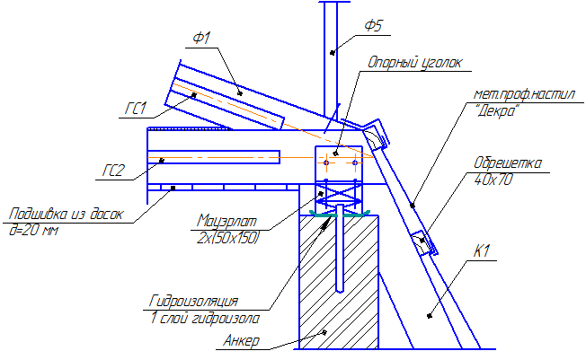
Figure 10.13 - An example of a wooden roof assembly
On the roofs of multi-storey buildings, for safety, it is necessary to install an enclosing parapet located above the eaves. For roofs with external drainage, the parapet is made in the form of a railing. For roofs with internal drainage, the parapet is made from the material of the outer walls, improving the architectural design of the facade of the building and hiding the protrusions of the ventilation and smoke blocks.
stairs are load-bearing elements that provide communication between floors. The stairwell is the part of the building where the stairs are located. The staircase consists of marches and landings. Flights of stairs are inclined elements with steps. Landings are called horizontal elements of the stairs, on which marches rest. Marches connect two landings, which carry out the transition from one march to another and the entrance to the premises (apartment, lobby, corridor, etc.). Stair flights and landings are currently made mainly of reinforced concrete.
Ramp is a flight of stairs without steps. The capacity of the ramp is much greater than the stairs, and it is much easier to climb it, because. the slope of the ramp is small from 5 to 12%. The use of the ramp is limited due to the large loss of usable area. Currently, the ramp is mainly used in multi-storey garages.
elevators are arranged in residential and public buildings with a height of more than five floors, as well as in industrial and warehouse buildings for the movement of industrial products and materials. All buildings and structures equipped with elevators also have stairs. Elevator shafts are made of fireproof materials and have exits on each floor. Elevator cables are designed for tenfold overload.
Window provide lighting and ventilation. The window unit consists of a window frame, glazed sashes, a window sill and an external drain. The window block box is inserted into the window opening and secured with metal crutches and wooden plugs. Window frames are hung to the window frame with the help of hinges. Vertical bindings are called sashes, and horizontal ones are transoms. Casements and transoms can be opening And deaf. Windows are single-leaf, double-leaf, three-leaf. In residential buildings, window openings are often combined with a balcony doorway. Windows come with single, double and even triple glazing. Double glazing is more common. Single glazing is used in buildings built in warm regions with positive day and night temperatures during the cold season, and triple glazing is used in areas of the Far North.
doors provide an entrance to the premises (house, apartment, rooms, halls, etc.). The door unit consists of a door frame and door panels. Usually, single-leaf and double-leaf doors are used, but sometimes glazed multi-leaf doors are arranged to increase the space between two adjacent rooms. According to the method of opening, the doors are divided into: swing, opening in one or both directions, sliding, rotating - turnstiles, folding, folding and lifting.
The type and dimensions of windows and doors, as well as the dimensions of window and door openings, are regulated by GOSTs.
10.7 Drawings of facades, plans, sections
10.7.1 Plan drawings
The plan is a section of the building and structures imaginary horizontal plane. For residential and public buildings, this plane passes within the door and window openings by about 1/3 of the height of each floor, and for industrial buildings at a height of 1 m from the floor level (Figure 10.14).
The building plan is included in the main set of architectural and construction drawings, which gives an idea of the configuration and dimensions of the structure, reveals the shape and location of individual rooms, window and door openings, main walls, columns, stairs, partitions, sanitary equipment, smoke and ventilation ducts and etc. plans for residential and public buildings often show the placement of furniture and other equipment.
On the plans of industrial buildings, as a rule, various technological equipment, crane tracks, rail tracks, etc. are indicated.
The plans of amenity premises of industrial buildings indicate the location of cabinets, hangers, benches and other equipment (Figure 10.15).
The structures on the plans and section are depicted in a simplified way without detailing. In large-panel buildings, window openings are depicted without quarters. If the floor plans differ from each other in the arrangement of individual sections of the outer walls, then a plan of one floor is drawn, and according to its example, ribbon plans of different sections of the walls are located. With a two-tier arrangement of windows in a building, the opening of the lower tier is shown on the main plan. The plan of wall sections with openings of the second tier is located along the perimeter of the main plan in the form of separate ribbons. A complex section of the plan is carried out on separate fragments, made on a larger scale and with a greater degree of detail. For residential buildings of great length, plans of individual sections are drawn on a larger scale. Residential sections are several one, two, three, four or more room apartments located near the stairwell. Floor plans, basements, technical underground, attic, ceilings, roofs, installation plans, etc. differ.
On the floor plans, the following are applied: the coordination axes of the building and structures, dimensions that determine the distance between the coordination axes and openings, marks of sections located at different levels, cut lines drawn in such a way that openings of windows, doors, external gates, etc. .d., positions (brands) of building elements, filling in the openings of gates and doors, lintels, stairs, etc., designation of nodes and fragments of plans, names of premises, technological sections, their area, categories for explosion and fire hazard, zone boundaries movement of technological cranes.
Positional designations of gate and door openings are indicated in circles with a diameter of 5 mm. Categories of technological sections are put down under their name in a rectangle 5x8 mm in size. Built-in premises and other structures on which separate drawings are made are depicted schematically as a solid thin line showing load-bearing structures. Platforms, mezzanines and other structures located above the cutting plane are depicted schematically by a dash-dotted thin line with two points. According to GOST 21.101, the floor plans are accompanied by: a list of lintels, a specification for filling elements of window, door and other openings, shield partitions, lintels marked on the plans, sections and facades.
On floor plans, the following are applied: extreme coordination axes, coordination axes at expansion joints, along the edges of sections with various structural and other features with dimensional references of such sections, designations of floor slopes, type of floors, marks in places of difference.
The walls of the building and partitions on the floor plans are depicted as one continuous thick main line. The floor plans indicate building elements and devices that affect the floor structure (gate and door openings, expansion joints, channels, ladders, etc.), as well as the boundaries of areas with different floor designs.
Expansion joints are depicted by two thin solid lines, and the boundaries of the floor sections are shown by dotted lines.
It is allowed to combine floor plans with floor plans.
The following are applied to the roof (roof) plans: extreme coordination axes, coordination axes at expansion joints, as well as along the edges of roof sections with various structural and other features with dimensional references of such sections, designations of roof slopes, marks or a schematic transverse profile of the roof, positions (marks ) roof elements and devices, parapet slabs and other elements of roof fencing, funnels, deflectors, ventilation shafts, fire escapes.
The coordination axes of buildings and structures on the plans are applied by dash-dotted lines with long strokes 0.3-0.4 mm thick. The center axes are taken out of the contour of the walls and marked. The marking of axes on the side of the building with a large number of load-bearing walls and columns is made by Arabic numerals 1, 2, 3 ..., which most often run across the building. Marking of axes on the side of the building with a smaller number of them is made in capital letters of the Russian alphabet A, B, C ... Such axes, in most cases, go along the building. The axes of the elements located between the center axes of the main supporting structures are marked with a fraction B / 1, ... G / 3, ... 2/1, ... 5/1, etc.
Drawing floor plans begins with the drawing of coordination axes. The first line of dimensions is drawn from the coordination axis at a distance of 20-30 mm, and the rest at a distance of 8 mm from each other. Therefore, it is necessary to have a total space around the building for drawing extension and three dimension lines, as well as marking circles with a total size of approximately 50 mm.
After drawing the coordination axes, the thickness of the outer walls is drawn. For example, if the thickness of the outer brick wall is 510 mm, the binding of the axis inside the wall will be 100 or 200 mm, and outside 410 or 310 mm, respectively. Capital interior walls are drawn symmetrically about the coordination axis. After that, the type of window and its dimensions are selected, taking into account the norms of illumination and the architecture of the facade. The height of the windows is taken constant for the entire floor, only their width varies. In the drawings of the technical project, window openings are drawn without window frames, bindings and window sills.

Figure 10.14 - An example of a floor plan design

Figure 10.15 - Floor plan of an industrial building with the arrangement of technological equipment
After breaking down the window openings, the dimensions of the windows are plotted in quarters, then the quarters are drawn so that the window expands inward, up to a size equal to two quarters. On the first dimension line, the size from the end of the wall to the window is indicated, and then the dimensions of the windows in quarters and the dimensions of the wall openings. The width of single-leaf windows according to GOST is taken equal to 720 and 870 mm, double-leaf windows - 1170, 1320, 1470 mm, three-leaf windows - 1770 and 2070 mm. Then partitions and doorways are drawn. The doorway on the plan is drawn with reference to one of the nearest walls. In this case, the brand of the door is affixed. Door sizes are assigned according to GOST: external double-leaf entrance doors are taken to be 1390 and 1790 mm in width, and 2300 mm in height, in rooms the width of double-leaf doors is taken to be 1202 mm, and single-leaf 800 and 900 mm 2000 mm high. In kitchens, bathrooms and pantries of residential buildings, single-leaf doors with a height of 2000 m are installed. The width of the doors to the kitchen is 700 mm, and in bathrooms and pantries - 600 mm. Single doors from the apartments to the stairs, to the common apartment corridor or to the floor vestibule should open inside the apartment. Double doors can open in different directions. In public buildings, doors to the stairwell, in common corridors, as well as doors intended for evacuation, must open towards the exit. The location of the door panels is applied on the building plan in accordance with GOST 21.107-78. Furnaces and stoves on the plan are located near the main walls, where smoke channels are provided. Ventilation ducts in the walls of kitchens, latrines and bathrooms are depicted as rectangles 140x140 mm or 140x270 mm in size, and smoke ducts - 140x270 mm in size. The plans indicate the thickness of the internal walls and partitions, the binding of the edges of the internal walls and partitions to the coordination axes or to the surface of opposite walls, the net distance between the main walls, as well as between the partitions in the rooms, the area of the rooms and utility rooms (kitchens, corridors, bathrooms, bathrooms). , pantries, etc.).
Roof plan is a view of the building from above. All roof slopes (roofs) have the same slope, therefore, the edges between the edges of the roof on the plan are angle bisectors. The roof plan is usually drawn on a scale of 1:200. Figure 10.16 shows the plan of a hipped roof.

Figure 10.16 - Plan of a hipped roof
10.7.2 Drawings of frontal and profile sections
On architectural and construction drawings, frontal or profile sections are usually drawn, obtained as a result of crossing the building with the corresponding vertical cutting planes. Sometimes the building is intersected by parallel planes, resulting in a complex stepped section. The sections are drawn based on the floor plans and the roof plan. Stairs are drawn simultaneously both on plans and on sections. The sections serve to reveal the constructive solution of the building and structure, the relative position of their internal premises, individual structures, heights, etc. Sections are divided into architectural and constructive.
architectural cuts(Figure 10.17) reveal the compositional aspects of the internal architecture of the building. On the architectural section, with the help of marks, indicate the height of the room, window and door openings, the basement, etc. Architectural sections are drawn up at the initial design stage to work out the facade of the building. They are not indicated by the construction of foundations, ceilings and coatings.
Structural cuts are part of the working drawings of the project. They present the structural elements of the building, their dimensions and marks. The direction of view for cuts is taken according to the plan from bottom to top and from right to left. For a profile (cross section), the cutting plane is placed perpendicular to the roof ridge or the largest building size. For a frontal (longitudinal) section, the cutting plane runs parallel to the ridge of the building or its largest size. At the same time, in all cases, the cutting plane should intersect the most structurally important parts of the building: window and door openings, flights of stairs and landings, elevators, balconies, etc.
If, when constructing a frontal section, the cutting plane runs parallel to the roof ridge, then the section is still made as if it cuts the building along the ridge. The cutting plane cannot be drawn through columns, racks, along the beams of walls and partitions. It must be placed between these structures. In this case, the contours of the foundations for columns and racks are drawn with invisible contour lines. On the frontal and profile sections of buildings, not all elements located behind the cutting plane are depicted, but only those that are in close proximity to it: columns, trusses, stairs, elevators, etc.
On sections of buildings without basements, soil and structural elements located below strip foundations and foundation beams are not shown. In sections, the floor on the ground is depicted as one solid thick line.
The floor on the floor and roofs is drawn with one continuous thin line, regardless of the number of layers in their construction, and the design and thickness of the floor are indicated in the external inscription.
In typical projects, sections of buildings and structures are divided into two parts. The first part is used for the construction of the underground part: foundations, technical basement, etc., and the second part is used for the construction of the ground part of the building. This is due to the linkage of a typical project to a real construction site, where most of the changes relate to the underground part (zero cycle).
The following are applied to the sections of buildings: coordination axes passing in the characteristic places of the section with dimensions that determine the distance between the axes and the total distance between the extreme axes, marks characterizing the location of elements of load-bearing and enclosing structures in height, dimensions and height bindings of openings, holes and sockets in walls and partitions shown in sections, positions (brands) of building elements not indicated on the plans, type of filling of window openings, material of individual sections of walls that differ from the main materials, designation of nodes and fragments of sections.

Figure 10.17 - An example of a section of a residential building
10.7.3 Execution of facades
The facade of a building is its orthogonal projection onto the frontal plane. It is built as a third projection according to two data - a plan and a section. The facade gives an idea of the appearance of the building and structure, its architecture and the ratio of its individual elements. The facades of buildings and structures are divided into the main facade, courtyard facade and side end facades. The main facade is considered to be from the side of the street or square. The facade is drawn above the building plan in the same scale. With a complex building configuration, facades located in different planes are depicted in separate drawings. The name of the facades is indicated by the numbers of the extreme coordination axes, for example, “Facade 1-12”, “Facade A-G”, etc. The name of the facade is written above its image. The drawings of the facades indicate: extreme coordination axes and coordination axes in places of ledges in the plan and differences in the heights of buildings, ground level marks, entrance platforms, facade structures located at different levels, brands of window blocks or types of filling of window openings not shown on the plans, sizes and bindings of elements not identified on the plans, sections and fragments, fire escapes, outdoor drains, lanterns, stained-glass windows, breaking walls into blocks and panels, expansion joints, ramps, louvered grilles installed instead of window parapets, balconies, lanterns of industrial buildings and etc. The degree of detail when drawing the facades of civil and industrial buildings depends on the scale.
So, for example, the drawing of window frames, the type of doors and gates are indicated only on facades drawn on a scale of 1:100 and larger; at smaller scales, only the contours of sashes and openings are drawn. On the main drawing of the facade, there should be a link to fragments of its complex sections, indicating the number of the sheet on which they are placed. In buildings made of prefabricated large blocks, panels, etc. facade fragments are not drawn, but filled with links to wall or facade layouts.
The drawing of the facade of the building is drawn in the following sequence: a straight horizontal line of the base of the facade is drawn with a thickness adopted for tracing the facades and taken out of the contour of the facade by 30 mm; draw a second horizontal line of revenge at a distance of 1.5 mm from the first; thin lines draw horizontal contours of the basement, bottom and top of window and door openings, cornice, ridge and other elements of the building; draw balcony railings, chimneys and ventilation pipes, dormer windows, parapets and other architectural details, apply reference circles, designate facade elements depicted on fragments, circles of coordination axes, extension lines, signs and dimensions of elevations, marks of axes, dimensions and all required inscriptions.

Figure 10.18 - An example of a side facade
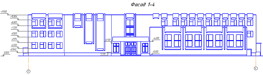
Figure 10.19 - An example of the design of the main facade of the school

Figure 10.20 - An example of the design of a fragment of the facade of an industrial building
House drawing - facade and floor plan
How is the drawing of the facade of the building carried out in accordance with the current standards and rules? What are the different projections of a building called?
Let's get acquainted with the general rules for the execution of construction drawings.
In the photo - a sketch of the facade of those times when the requirements for project documentation differed from the current ones.
General provisions
The answer to the question of how to draw the facade of a building, we will begin by listing the requirements common to all construction drawings and diagrams.
Terminology
- All construction drawings are obtained by projecting a certain type of building onto a plane.
- The actual drawing of the facade of the house is its frontal projection onto a plane parallel to the facade .
- The projection of a section of a building in a longitudinal or transverse plane is, respectively, a longitudinal or transverse section.
- If a horizontal section of a building is transferred to paper, it is commonly called a plan. Depending on the level at which the cut is made, it can be a basement plan, a first floor plan, and so on.
- A top view of a site that includes a building or a group of buildings and structures is commonly called a master plan.
- Finally, no matter what object is depicted - the basement of a kindergarten, the facade of an industrial building, the facade of a cottage, the facade of a cafe or a toilet in a summer cottage - all these images have a common name: architectural and construction drawings.

Despite the spread of electronic media, the drawings must be printed on paper.
Regulations
Sections, plans and drawings of building facades must be made in a common ESKD system (unified system for design documentation). Its standards are determined by GOST 2.301-68 - GOST 2.307-68.
What exactly is regulated?
- Sheet formats for all drawings.
Important: format requirements imply certain aspect ratios of the sheet itself, and not the drawing frame.
- Scale series of images.
- Line thickness.
- The name of the image elements.
- Drawing fonts.
- Image methods on the drawings of various objects.
- Graphic designations of various materials.
The following scales can be used when drawing up master plans for objects:

In the drawings of facades and plans, of course, larger scales are also used.
A 1:1 scale can be used when transferring complex-shaped cornices and other small elements onto paper. However, this is rather an exception. Zoom scales are not used in architectural and construction drawings.
Rules for the execution of drawings
In order to correctly make drawings of house facades, floor plans and other architectural and construction schemes with your own hands, you need to adhere to fairly strict rules.
- The thickness of the main line must be the same for all details of the drawing, performed on the same scale. An exception is sectional drawings: visible contour lines can be drawn with a thin line.
- Names, headings and designations in the drawing field can be written without inclination. But the dimensions and other inscriptions on the arrows are written obliquely, with an angle relative to the base of the line of about 75 degrees.
- The total number of dimensions in the drawing should be, as common sense suggests, sufficient for construction work. In this case, duplication of the same size on different elements of the image is allowed.
- Dimensions are given in millimeters without indicating units of measurement. However, the level above the ground is indicated in meters to the third decimal place.

Traditionally, all dimensions in the drawings are indicated in millimeters. The rule is not absolute; but other units of measurement should be indicated in the notes.
Attention: it is permissible to indicate dimensions in centimeters, provided that the units of measurement are specified in the note to the drawing. And in this case, the units of measurement are not specified separately.
Features of drawings of facades
We have listed the general provisions. Are there any nuances associated specifically with the facades that interest us primarily? How to draw the facade of the building in accordance with the current rules?
- The drawing of the façade should give a clear idea of the appearance of the façade of the building (see beautiful facades of private houses), the proportions and size of individual elements.
- If the facade and the plan are on the same drawing, they are performed on the same scale and must be in projection connection. What does this mean? Only that the plan is located on the drawing under the facade.
- The facades of different sides of the building have their own names, which are indicated on the drawing. There are main, courtyard and side (end) facades.
- The drawing indicates all the structural details that will be present in a real building. For example, the main facade of the school in the drawing should be equipped with a porch, the yard facade with a fire escape; cornices, dormer windows and other seemingly trifles are drawn.
- In a technical project, it is customary to show its own shadows and the shadows falling on it on the facade. To do this, the drawing is painted with watercolors or shaded with dry grated ink.
- The facade drawing does not indicate the horizontal dimensions. However, on the one hand, at a distance of 15-20 millimeters from the contour of the facade, general height dimensions and level marks for the ground, windows and doors, plinth, eaves and ridge of the roof and the top points of pipes and ventilation are affixed.
- At the bottom of the facade, axes of expansion joints and differences in the height of the building are applied.
Before us is a drawing of the facade made in accordance with all the rules. Quite complex, I must say. It was taken from a very real building - the Bolshoi Drama Theater on the Fontanka embankment in St. Petersburg.
Conclusion
You can find more information about building drawings at the end of the article. In addition, it is useful to know that the price of the design is the project of the facade and floors of the cottage. including a complete set of drawings, starts from 10,000 rubles for standard solutions. Exclusive projects can cost ten times more. Successes in construction!


